Download
1 / 41
410 likes | 428 Views
Discussing the benefits of modular partitioning in VHDL design, exploring hierarchy trees, design libraries, design units, and best practices for structural style architectures. Learn through examples like a full adder design.

E N D
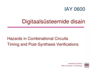
Alexander Sudnitson Tallinn University of Technology IAY 0600Digital Systems Design VHDL discussion Structural style Modular design and hierarchy
Hierarchy tree for the modular partition There are tradeoffs in deciding the complexity of a leaf nodes, such as code readability and maintainability, module reuse, and synthesis and verification efficiency.
Advantages of good design partition • Design management is easier • Modules can be designed and verified by different individuals • Maximum reuse of modules is made possible • The design description is more readable and easier comprehend • Verification is simplified • Better design results are likely • The portability of the design is enhanced
A simple example (full adder) Modular and hierarchical designs are implemented in VHDL using structural stylearchitectures. A structural architecture is, ultimately, a collection of design entities interconnected by signals.
Hierarchy tree for a full adder The partitioning process is continued until each leaf node representsa relativelysimple module that we can easily comprehend and directly code.
Design file and design units A name made directly visible to a primary library unit by a context clause isautomatically visible in any associated secondary library unit.
Design libraries A simulator can only simulate programs that have been successfully compiled and stored in a library. A design library is a logical storage area in the host computer environment for compiled design units (library units) A design library is identified by its logical name. There are two kinds of design libraries: working library and resource library
Design libraries All VHDL compilers come with the library STD included. This built-in library is provided by standard IEEE Std 1076. Library STD contains two packages: STANDARD and TEXTIO. VHDL compilers also include the library IEEE. This library contains packages defined by VHDL’s supporting standards, such as packages STD_LOGIC_1164. Of course, we can write our own packages and place them in libraries that we create – user-defined libraries. Third-party intellectual property provides sell libraries containing complex design entities that we can use as modules. PLD vendor libraries (Source code for the architecture bodies and package bodies is usually not provided)
Using library units • Implicit context clause: • Every library unit is assumed to be preceded by the implicit context clause • librarystd, work ; • usestd.standard.all ; • Rules: • A primary unit whose name is referenced within a given design unit must be compiled prior to compiling the given design unit. • A primary unit must be compiled prior to compiling any associated secondary units. • User written packages and other design units can beprecompiled and placed in aresource library. Design entities in a resource library can be used as modules bydesign entities in a design file. The appropriate context clauses for any resourcelibraries used must be included prior to each library unit in a design file.
Design file and design units A design unit is a VHDL construct that can be construct that can be independently compiled and stored in a design library. Design units provide modularity for the design management of complex systems. A design file is a source file containing one or more design units. A design file is the input to a VHDL compiler. Design units in a design file are compiled in the same order as their textual order in the file. Using separate files allows separate compilation and verification of each design entity.
Description in a single design file -1- library ieee; use ieee.std_logic_1164. all ; entity half_adder is port (a, b : in std_logic; sum, carry_out : out std_logic); end half_add; architecture dataflow of half_adder is begin sum <= a xor b ; carry_out <= and b ; end dataflow ; library ieee; use ieee.std_logic_1164. all ; entity or_2 is port (a, b : in std_logic; sum, or_out : out std_logic); end or_2; architecture dataflow of or_2 is begin or_out <= a or b ; end dataflow ;
Description in a single design file -2- library ieee; use ieee.std_logic_1164. all ; entity full_adder is port (a, b, carry_in : in std_logic; sum, carry_out : out std_logic) ; end full_add; architecture structure of full_adder is signal s1, s2, s3 : std_logic ; begin ha1 : entity half_adder port map (a => a, b => b, sum => s1, carry_out=>s2); ha2 : entity half_adder port map (a =>s1, b =>carry_in, sum =>sum, carry_out =>s3); or1 : entity or_2 port map (a => s3, b => s2, or_out => carry_out) ; end structure ;
Design file containing top-level entity - - The half_adder and OR gate design entities have been compiled - - to a user-created library called parts. library ieee; use ieee.std_logic_1164. all ; library parts ; use parts.all ; -- user-created library entity full_adder is port (a, b, carry_in : in std_logic; sum, carry_out : out std_logic) ; end full_add; architecture structure of full_adder is signal s1, s2, s3 : std_logic ; begin ha1 : entity half_adder port map (a => a, b => b, sum => s1, carry_out=>s2); ha2 : entity half_adder port map (a =>s1, b =>carry_in, sum =>sum, carry_out =>s3); or1 : entity or_2 port map (a => s3, b => s2, or_out => carry-out) ; end structure ;
Closer look at structiral design In a structural style description, component instantiation statements are used tocreate an instance of each design entity. The syntax provides two forms for a componentinstantiationstatement: 1) Direct instantiation of a design entity. 2) Indirect instantiation. Indirect instantiation instantiates a component,which serves as a placeholder for a design entity rather than directly instantiating adesign entity. The binding of each component to an actual design entity is then accomplishedusing either default binding or an explicit binding indication.
Direct instantiation of design entities • Consider a following example. Assume that we have created separate design files for each of the following entity declarations and architecture bodies and compiled them into our working library in the order listed: • Entity and_2 • Architecture dataflow of and_2 • Architecture behavioral of and_2 • Entity or_2 • Architecture dataflow of or_2 • We now want to use these entity in a structural style description of the simple combinational circuit (next slide) The order of compilation
Direct instantiation of design entities Binding is the process of associating a design entity and, optionally, a specific architecture body with an instance of a component. library ieee; use ieee.std_logic_1164. all ; entity comb_ckt is port (a, b, c, d : in std_logic; f : out std_logic) ; end comb_ckt; architecture structural_1 of comb_ckt is signal s1 : std_logic ; begin u1 : entity and_2 port map (in1 => a, in2 => b, out1 => s1) ; u2 : entity and_2 port map (in1 => c, in2 => d, out1 => s2) ; u3 : entity or_2 port map (in1 => s1, in2 => s2, out1 => f) ; end structural_1 ;
Default binding rules The compiler can follow a set of default binding rules, defined in the LRM, to accomplish bindings. For example, by default compiler looks in the working library (work) for an entity declaration whose name and interface match those specified in the component instantiation statement. If, in the working library, there is more than one architecture body associated with that entity declaration, then the compiler uses the one most recently compiled. For entity and_2 (previous slide), there are two possible architectures: dataflow and behavioral. Assuming that behavioral was the most recently compiled, instances u1 and u2 will both use that that architecture body. If we want binding other than default binding, we can specify the desired architecture with the entity name in the component instantiation statement. u1: entity and_2 (dataflow) port map (…); u2: entity and_2 (behavioral) port map (…); Specifying the library: u1: entity work.and_2 (dataflow) port map (…);
Components and indirect instantiation Indirect design entity instantiation uses a placeholder, called a component, to stand for the design entity in a component instantiation statement. Thus a component can be viewed as a virtual design entity. Look next slide. First, each component must be declared before it can be used. Second, each instantiation statement is an instance of a component, not an instance of a design entity A component declaration is placed in the declarative part of the architecture in which the component is used. Alternatively, if a component is likely to be used in multiple designs, its declaration can be placed in a package in a library.
Indirect instantiation of design entities -1- library ieee; use ieee.std_logic_1164. all ; entity comb_ckt is port (a, b, c, d : in std_logic; f : out std_logic) ; end comb_ckt; architecture structural_2 of comb_ckt is component and_2 is port (in1, in2: in std_logic ; out1 : out std_logic) ; end component ; component or_2 is port (in1, in2: in std_logic ; out1 : out std_logic) ; end component ;
Indirect instantiation of design entities -2- signal s1, s2 : std_logic ; begin u1 : component and_2 port map (in1 => a, in2 => b, out1 => s1) ; u2 : component and_2 port map (in1 => c, in2 => d, out1 => s2) ; u3 : component or_2 port map (in1 => s1, in2 => s2, out1 => f ) ; end structural_2 ;
Components and configuration specification • For components, there are three ways that binding can be accomplished: • Default binding • Configuration specification • Configuration declaration • In contrast to default binding, use of a configuration declaration or specification allows us to explicitly specify bindings. • Configuration specifications are place in the declarative part of the architecture in which the components are instantiated. • A configuration declaration is a design unit. • A configuration specification starts with a keyword for.
Components and configuration specification library ieee; use ieee.std_logic_1164. all ; entity comb_ckt is port (a, b, c, d : in std_logic; f : out std_logic) ; end comb_ckt; architecture structural_3 of comb_ckt is component and_2 is port (in1, in2: in std_logic ; out1 : out std_logic) ; end component ; component or_2 is port (in1, in2: in std_logic ; out1 : out std_logic) ; end component ;
Components and configuration specification signal s1, s2 : std_logic ; -- configuration specifications for u1 : and_2 use entity work.and_2(dataflow) ; for u2 : and_2 use entity work.and_2(behavioral) ; for u3 : or_2 use entity work.or_2(dataflow) ; begin u1 : and_2 port map (in1 => a, in2 => b, out1 => s1) ; u2 : and_2 port map (in1 => c, in2 => d, out1 => s2) ; u3 : or_2 port map (in1 => s1, in2 => s2, out1 => f ) ; end structural_3 ;
Components and configuration specification There are two fundamental differences in Listing slides 21-22 and Listing slides 24-25: 1) each component in Listing slides 24-25 must be declared before it can be used, 2) each instantiation statement is an instance of a component, not an instance of a design entity.
or_3 desig entity bound to u3 or_2 Let us consider the following example. The configuration specification for u3 could be written as for u3 : or_2 use entity work.and_2(dataflow) ; and no compilation error would occur. But, the function of the resulting combinationa circuit has been changed (the effect of using this configuration specificationis shown in next slide).
Port maps in configuration specification For example, assume that we did not have a design entity or_2 to bind to component or_2, but we did have a three-input OR designentity in the library parts (full adder example). Assume that the entity declaration is entityor_3 is port (inp1, inp2, inp3 : in std_logic; outp1 : out std_logic) ; end or_3; We can changethe configuration specification for u3 to for u3 : or_2 use entity parts.or_3(dataflow) ; port map (inp1 => in1, inp2 => in2, inp3 => ´0´, outp1 => f) ;
Configuration declaration Using configuration specifications is advantageous whenwe don’t intend to change our component-instance/design-entity bindings. Greaterflexibility in specifying bindings can be achieved using a configuration declaration. A configuration declaration is a design unit that allows bindings of architecturebodies to entity declarations, as well as bindings of components to design entities, to bespecified. Since a configuration declaration is a separate design unit, these bindings arespecified outside of the architecture body.
Configuration declarationfor comb_ckt Configuration declaration specifying architecture dataflow. configuration config1 of comb_ckt is for dataflow --block configuration end for; end config1; The simplest use of a configuration declaration is to specify the binding of an architecture to a design entity when the architecture is not structural. Suppose that we had a second architecture for comb_ckt that was a dataflow architecture named dataflow. We now have two different architectures for design entity comb_ckt. If we simulated comb_ckt, by default, the most recently compiled architecture would be used. Suppose that we wanted to simulate comb_ckt using the dataflow architecture and it was not the most recently compiled. We could create a configuration declaration to specify that architecture dataflow be used.
Con. dec. for comb_ckt (component configurations) -1- configuration config2 ofcomb_cktis for structural_2 -- block configuration for u1 : and_2 -- component configuration use entity work.and_2(dataflow); end for; for u2 : and_2 -- component configuration use entity work.and_2(behavioral); end for; for u3 : or_2 -- component configuration use entity work.or_2(dataflow); end for; end for; end config2; To write a configuration declaration for design entity comb_ckt that uses architecture structural_2 (slide 21-22), we must not only specify the architecture,but also the bindings of components in the architecture to design entities. This is accomplished using component configurations inside the configuration declaration.
Con. dec. for comb_ckt (component configurations) -2- A component configuration inside of a component declaration allows us to configure the internal structure of the architecture of an entity to which a component is bound; a configuration specification does not allow this. The of a component configuration is like that of a configuration specification, except for the addition of the keywords end for.The architecture (slide 21-22) for structural_2 contained no configuration specifications, and its components were bound to design entities using default binding. Configuration declaration config2 explicitly configures this architecture to produce the same bindings that were produced using configuration specifications in slide 24-25.
Generate statement A generate statement is a concurrent statement that allows us to specify the replication of concurrent statements. If a concurrent statement that is to be replicated is a component instantiation statement, then we have a concise way of describing the repeated instantiation of a component. Syntax for a generate statement
Generate statement (example) entity d_ff_pe is port (d, clk: in std_logic; q: out std_logic; end d_ff_pe; architecture behavioral of d_ff_pe is begin process (clk) begin if clk'event and clk = '1' then q <= d; end if; end process; end behavioral; Assume that we have compiled this D flip-flop description to the working library.
Serial-in parallel-out 4-bit right-shift register A 4-bit shift register described using an iterative generate statement entity is port (si : in std_logic; clr_bar : in std_logic; clk : in std_logic; qout : out std_logic_vector (3downto0)); end shift_reg_gen; architecture structural of shift_reg_gen is signal s: std_logic_vector (4 downto0); begin stages: for iin 3 downto0 generate begin stage: entity dff_stage port map (d => s(i + 1), clr_bar => clr_bar, clk => clk, q => s(i)); end generate; s(4) <= si; qout <= s(3 downto0); end structural;
Serial-in parallel-out 4-bit right-shift register A 4-bit shift register described using an iterative generate statement The discrete range of the generate statement is from 3 down to 0. The component instantiation statement inside the generate statement generates the four instances of the D flip-flop. The connection of the serial input si to the D input of the leftmost flip-flop is made by the concurrent statement s(4) <= si; which is outside of the generate statement. The connection of the D flip-flop outputs to the output port qout is made by the concurrent statement qout <= s(3 downto 0); which is also outside of the generate statement.
Alternative architecture body for the shift register architecture structural2 of shift_reg_gen is signal s: std_logic_vector(3 downto0); begin stages: for i in 3downto0 generate begin lstage: if i = 3 generate begin stage: entity dff_stageport map (d => si, clr_bar => clr_bar, clk => clk, q => s(3)); end generate; ostages: if i /= 3 generate begin stage: entity dff_stage port map (d => s(i + 1), clr_bar => clr_bar, clk => clk, q => s(i)); end generate; end generate; qout <= s(3 downto0); end structural2;
Alternative architecture body for the shift register In the architecture body an iterative generate statement labeled stages sequences through the values of its generate parameter. Nested inside this generate statement are the two conditional generate statements. The first conditional statement, labeledlstage, has the condition i = 3. When the generate parameter is equal to 3, this conditional generate statement produces the instantiation of the leftmost stage of the shift register. The second conditional statement, labeledostage, has the condition i/= 3. When the generate parameter is not equal to 3, this conditional generate statement produces the instantiation of the other three stages of the shift register.
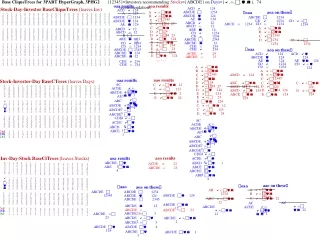
Serial-in parallel-out 4-bit right-shift register Logic synthesized for 4-bit shift register