Download

1 / 18
180 likes | 193 Views
This article discusses the importance of module structure in software design, specifically focusing on coupling and cohesion. It explains the different types of coupling and levels/types of cohesion, and highlights the relationship between cohesion and coupling. The article also introduces the concept of functional-oriented design and discusses the use of structure charts and pseudocode in system design.

E N D
Design • Module view • What module should the system and which have to be developed . • It determines the module structure of components.
Coupling • It is the measure of the degree of interdependence between modules. • Coupling between the modules is the strength of interconnection between modules or a measure of interdependence among modules. • Highly coupled – strong interconnection • Loosely coupled- weak interconnection
Factors Affecting Coupling • Number of interfaces increases coupling. • Complexity of interface • Type of info flow along interfaces • Data • control
Types of coupling • Data coupling: The dependency b/w module A and B is said to be data coupled if their dependency is based on the fact they communicate by only passing of data. • Stamp Coupling: When complete data structure is passed from one module to another. • Control Coupling: Passing of control information. This is set by flags that are set by one module and reacted upon by the dependent module.
External coupling: Related to the communication external tools and devices. • Common Coupling: Module A and B have share data. • Content Coupling: Module A changes data of module B. A B C D
Cohesion • Cohesion is a measure of a degree to which the elements of a module are functionally related. • Cohesion of the module represents how tightly bound the internal elements of the module are to one another
Levels / Types of cohesion • Coincidental: X and Y here no conceptual relation ship other than shared code. • Logical: X and Y performs logically similar operations. • Temporal : Tasks that are related by the fact that all tasks must be executed in the same time span.
Procedural: Procedural cohesion occurs in modules whose instructions although accomplish different tasks yet have been combined because there is a specific order in which the tasks are to be completed. • Communicational: X and Y both operate on same input/ output data. • Sequential: X outputs some data which forms input to Y. • Functional: X and Y are a part of single functional task. Related to performing single function.
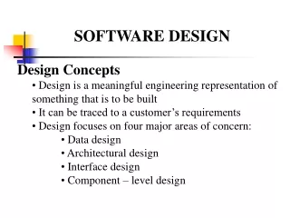
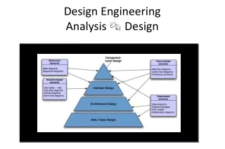
Functional oriented design • The design process for software systems often has two levels. • At first level the focus is on deciding which modules are needed for the system, their specification of these modules, and the modules should be interconnected. • Design is imposed on a set of interacting units where each unit has clearly defined functions.
This method works fine for small programs. • While(not finished) • { • Read an expression; • Evaluate the expression; • Print the value; • }
Print module • Print (expression exp) • { • Switch(exp->type) • Case integer • Print integer; • Case real • Print real; • }
Functional oriented design are represented as • DFD • Data Dictionary • Structure chart • Pseudo code Structure chart is one of the most commonly used method for system design. Black boxes are used.
Data • Control • Module • Conditional call of module
Pseudocode • Using Pseudocode, the designer describes system characteristics using short concise , english language phrases that are structured by keywords such as If then Else, Do while, end .
Relation Ship b/w cohesion and Coupling • A s/w engg must design the modules with goal of high cohesion and low coupling.