Download

1 / 25
260 likes | 458 Views
Ad-hoc network communication infrastructure for multi- robot systems in disaster scenarios. IARP/EURON Workshop on Robotics for Risky Interventions and Environmental Surveillance January 7th-8th, 2008 - Benicàssim. Ad-hoc network communication infrastructure

E N D
Ad-hoc network communication infrastructure for multi- robot systems in disaster scenarios IARP/EURON Workshop on Robotics for Risky Interventions and Environmental Surveillance January 7th-8th, 2008 - Benicàssim
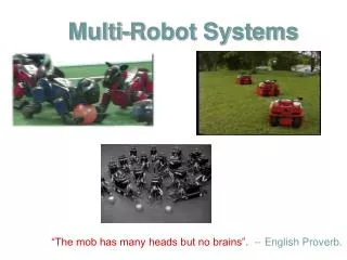
Ad-hoc network communication infrastructure for multi-robot systems in disaster scenarios Ulf Witkowski Mohamed El-HabbalStefan HerbrechtsmeierAndry Tanoto Heinz Nixdorf InstituteUniversity of Paderborn Jacques PendersLyuba Alboul Sheffield Hallam UniversityMicrosystems and Machine Vision Lab Veysel Gazi TOBB University ofEconomics and Technology, Dept. Electrical and Electronics Engineering • Introduction: GUARDIANS’ scenario • Objectives of the communication system • Swarming and positioning • Implementation – platform and features • Results
Introduction • Disaster Scenario: Burning large warehouse • Building with huge dimensions (>100m) • May be (partly) filled with black smoke • Technical infrastructure destroyed • Only local Communication betweenfirefighters (exchange of commands) • Orientation of firefighters by applying ropes with nodes indicating direction to exit • Team of robots assisting firefighters by (excerpt) • Searching and inspection of the building • Providing communication infrastructure (between firefighters, to operator,between robots and humans, robot-robot communication) • Providing position and orientation data • Guiding firefighters to the exit
Objectives of the communication infrastructureand networking • 1. Robust ad-hoc communication system for • Communication between • Humans (HSM – HSM, and HSM - operator) • Humans and robots (HSM commands/asks robots) • Robots (for cooperation) • to facilitate • Primarycommunication • Service discovery • Positioning • Navigational aid for fire fighters and robots • by • Combining three (and more) communication technologies(WLAN, Bluetooth, ZigBee, Chirp-ISM, UWB) • Plus all necessary layers of ISO/OSI model(including ad-hoc-networking, service discovery, and positioning) • Single antenna, multiple antennas, antenna arrays + MAC-Layer)
Objectives of the communication infrastructure • Communication system provides and uses position data • Useful data for the firefighters • Eases maintenance of the communication network • Enables position based / cell based service discovery • Supports map building (data for operator) Supports placement of nodes tospan the mobile ad-hoc network Supports service discovery(offering and accepting services)
Communication technologies • Existing radio based communication technologies • WLAN: • Max. number of nodes: not specified • Range: 100m (300m), data rate: 54 Mbit/s • Power consumption: high • Bluetooth: • Piconet: 8 nodes, Scatternet: Network of Piconets • Range: 100m, data rate: 2.1 Mbit/s • Power consumption: low • Cell forming by adapted frequency hopping • ZigBee: • Up to 255 nodes • Range: 75m, data rate: 250 kbit/s • Power consumption: very low • UWB: Excellent for positioning BUT bad availability • Nanoloc: Two way ranging in ISM band by using chirp signals • Accuracy of distance measurements: 1-2 m
Communication test platformHNI Minirobot System • Processor PXA270 520MHz • SDRAM 64MB • NOR Flash 64MB • FPGA Spartan3E 1600k Wireless Communication • ZigBee (UART) • Bluetooth (UART) • WLAN (USB-Adapter) Software • Linux Kernel 2.6.23 • Device Manager (udev) • GNU C Library (Glibc) 2.5 • Complete Linux environment (Debian like) • Automated build and packet system (OpenEmbedded) This robot together with Khepera III is used for experiments transfer to large robot (Robotnik) 68 mm 93 mm 86 mm
Communication architecture • Implementation of a mobile ad-hoc communicationframework for the Linux operating systemon the HNI-minirobot Communication Framework • Service Discovery: manage, publish andsubscribe of services (data) • Data Exchange implement data communication • Quality of Service (and Positioning) interact withapplication (swarming) to achieve stable networks Network Abstraction Layer • One common of interface to different networks • Development of a hardware module for integration intoother systems (Khepera III and later on Robotnik system)
Spanning a (mesh of) nodesfor a robust network Static nodes placement L 60 L Mesh of equilateral triangles (advantageous area coverage) Communication cell for mobile robots hand over between cells if required quasi static node (mobile robot, ordropped communication relay) • where L depends on : • Maximum radio range supported by the communication standard used • Maximum detection range supported by the distance sensor(Radar, ultrasonic, LRF or LIDAR, Radio ToF)
Swarming • Swarming is used to (among others) distribute the robots to span a robustcommunication network • Non communicative swarming • Loosely coupled entities withlocal interaction • Used as fall back if communication fails • Communicative swarming • as standard control mode for robots and the team • distribution of robots in a triangular grid • for supporting • Various cooperative behaviors (e.g. navigation, search/exploration,sensing, area coverage, gradient following, formation control, localization) • by • Heuristic/ad-hoc, artificial potential functions,gradient based, probabilistic, game theory, etc.
Static nodes placement Mode1 Mode1 d1 d1 d2 d2 Mode2 Placement modes
Static nodes placement Mode3 Mode1 Mode2 d2 d1 Placement modes
Experiments - Overview L 60 L • Hybrid solution for node control/placement: • Distance control <-> signal quality • Distance measurements • Laser range finder (LRF) and comm. • Aim: Place the third of three robots tothe correct position to span aequi-lateral triangle (part of the robot distribution scheme) • Experiments: • Signal quality measurements vs. distance (+obstacles)WLAN, Bluetooth, ZigBee • Radio based distance measurements(Several point to point measurements and calculation of robot’s psosition) • Angle measurements with LRF supported by communication(‘Third’ robot measures its angle to fixed robots by using LRF that can be rotated)
Experiment 1Signal quality measurements Signal quality measurements for WLAN, Bluetooth, and ZigBee Path length: approx. 90 m, area with path (30m x 15m)
Experiment 2Positioning system Scenario: 4 mobile robots, 3 of these are‘infrastructure’ robots with known positions, position of the 4th robot has to be determined all data is sent to local server, that display calculated and actual path of the 4th robot
Experiment 3LRF + communication • Active laser sensor(ifm-efektor LRF, • rotatable) • Robot base withcommunication module • Laser detector
Experiment 3LRF + communication • Mobile robot seeks to move to the desiredposition to complete the triangle • It sends the request to the other static nodes • Robot initiates wireless connection withthe 2 static nodes using Bluetooth. • After connection establishment, lasersensor on robot starts rotating and scanningfor the 2 static nodes. Robot gets feedback if nodes are hit by the laser beam • As the 1st node is hit, it sends a reply tothe robot, which stores the distanceat that instant, and inverses its rotationto search for the other node. • As the 2nd node is hit, same procedure occurs. Afterwards, using the necessarytriangulation algorithm, the robot calculates the desired angle to rotate and the desired distance to move to reach its goal.
Conclusion and Outlook • Ad-hoc communication network to support firefighters • Distribution of robots to span the network(infrastructure robots and mobile nodes) • Hardware platform combing WLAN, Bluetooth, ZigBee, and Chirp-ISM • Experiments for node placement • Accuracy analysis vs. requirements • Communication protocol
Thank you for your attention! http://www.shu.ac.uk/mmvl/research/guardians/
Minimizing interference 1 2 1 2 3 4 3 4 • FCC and ETSI radio rules for Bluetooth • v1.0 and v1.1: • Hopping channels: 78 (full spectrum) • Hopping rate: 1600 hops/s • v2.0: • Hopping channels: 15 (AFH) • Hopping rate: 1600 hops/s • By using Bluetooth v2.0, spectrum can be divided into 5 channel groups • 4 groups for intra-cell, and 1 group for inter-cell communication (static nodes) • A cell that requires more traffic can request the use of more channel groups • from adjacent cells if they are free to use.
Experiment 3LRF + communication • Used Hardware • Laser sensor : ifm-efektor LRF • Laser detectors : near visible Red photo-transistors • Communication devices : Mitsumi Bluetooth chips class-1 • Processing Board : • FPGA Virtex-E board with ADC
Experiment 3 • Procedure • Mobile robot seeks to move to the desired position to complete the equilateral • triangle. • It sends the request to the other 2 static nodes, which should guide him to the • correct position. • Robot initiates wireless connection with the 2 static nodes using Bluetooth. • After connection establishment, Laser sensor on Robot starts rotating and scanning • for the 2 static nodes. For each rotated step, it requests info from static nodes whether • they are hit by the Laser beam or not. • As the 1st node is hit, it sends a positive reply to the Robot, which stores the distance • at that instant, and inverses its rotation to search for the other node. • As the 2nd node is hit, same procedure occurs. Afterwards, using the necessary • triangulation algorithm, the Robot calculates the desired angle to rotate and the • desired distance to move to reach its goal. • In our demo, the Laser sensor just rotates with the desired angle and points at its goal. • Laser detectors : near visible Red photo-transistors • Communication devices : Mitsumi Bluetooth chips class-1 • Processing Board : • FPGA Virtex-E board with ADC
Example for determining the position withNanotron‘s nanoLOC RF Module • R1, R2 and R3 are the robots • with known coordinates • (infrastructure robots) • They drive to their position from • a common start point and • get their coordinates by • odometry • T is the robot which position • has to be calculated • The distance between R1 & T, • R2 & T and R3 & T is measured • with the Nanotron Transceiver • The position of T can be • calculated by solving a system • of equations.
Atmel ATmega128L implementation • Apart from a package switching process displayed in the following picture, a driver for • controlling the nanoLOC transceiver is running on the Atmel of the DK – boards • This driver is written by nanotron and contains some time critical passages for • ranging and it provides the ranging capabilities • The package switching process forwards communication packages in both direction and • filters ranging package from the PDA processor to start a ranging process