Download
1 / 41
410 likes | 542 Views
Cable Fire at the LER TFB Kicker. Stan Ecklund for investigation committee and other helpers. Investigation Committee. Ron Akre Stan Ecklund (Chair) Keith Jobe Joseph Olszewski Bob Reek Ponciano Rodriguez Mike Stanek Uli Wienands Andrew Young. Charge.

E N D
Cable Fire at the LER TFB Kicker Stan Ecklund for investigation committee and other helpers
Investigation Committee • Ron Akre • Stan Ecklund (Chair) • Keith Jobe • Joseph Olszewski • Bob Reek • Ponciano Rodriguez • Mike Stanek • Uli Wienands • Andrew Young PEP-II MAC Review
Charge 1. Research the sequence of events leading to the fire. Determine the cause of the fire, if possible, or determine probable causes. 2. Identify damage and recommend a course of action to repair or replace damaged equipment. 3. Based on determined cause, recommend changes to this and similar systems that will prevent future incidents. 4. Coordinate with the ORPS investigation (do not duplicate) PEP-II MAC Review
Location in PEP-II Region 4 PEP-II MAC Review
LER Horizontal Kicker 3040 PEP-II MAC Review
Transverse Kicker Pickup Structure This picture shows the kicker as a pickup. The picture below is the time domain response of a by4 fill pattern. If it was a by2 fill pattern, the signal in the red circle would move to the blue circle thus, the leading edge of the next bunch cancels the trail edge of the previous bunch. The round trip time(4.2ns) = 2L/c where L = 63cm PEP-II MAC Review
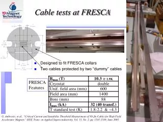
Kicker • 1.755” radius (44.577 mm) • 120 deg. • 24.62” long PEP-II MAC Review
Photo by David Kharakh on 11 Oct. 2005 PEP-II MAC Review
Photo by Mike Zurawel on Aug. 17 2006 PEP-II MAC Review
Wall Side PEP-II MAC Review
Breach in Cable PEP-II MAC Review
Melted center conductor PEP-II MAC Review
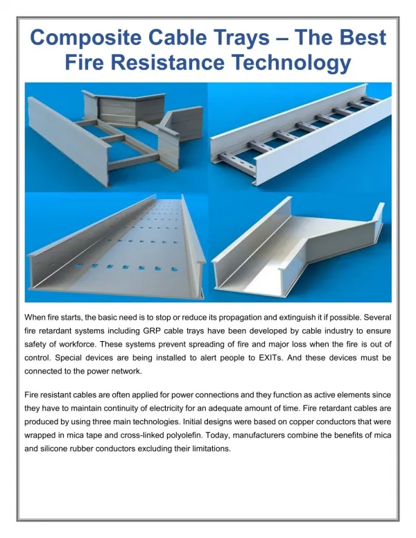
Cable Trays PEP-II MAC Review
Investigation Activities • Observe and document situation • Many Photos at: • V:\AD\AreaManagers\MZurawel\LER X Kicker 8-17 • Roped off Site to keep undisturbed during investigation • Calculated beam power to cables (Steve Smith, Andrew Young, Anatoly Krasnykh, John Fox) • Tested another fan, stalled • Looked at cable/tray damage • Mined history data PEP-II MAC Review
Event Sequence (Uli Wienands) • 2000 mA, 861 bunches, by-4 (0:3442:4) • 17:42 arc T3040Ki2 sees temp. rise • 17:46 arc T3040K14, K15 see temp. rise • 17:48 elog LER Abort with LR42 Latched • 17:50 elog Fire Alarm 3114 IR-4 Building • Starts in tunnel, then B645 (rf), then B640 (dnstairs)(no time line, just recollection) • 17:51:32 errlog PR03 174 trips on gnd fault17:51:52 errlog PR08 5162 trips mag. Intlk #2 • 17:53:12 errlog P2HZDSOFF started PEP-II MAC Review
Current and Temps Normal Run At time of fire HOM T3040KI2 X- Load Connector LER Current T3040K14 Body T3040K15 Bellows PEP-II MAC Review
TFB Drive Connections • Note A: Damage found in the output section of the amplifier, the output transistor not connected to circuit • Note B: Cable center pin was found not mating contact with filter. This causes the beam reflected signal to see an open at the amplifier • Note F: Fire damage. X- drive cable damage is present up to 5 m from the kicker PEP-II MAC Review
TFB Load Connections • Note C: A cable breach was discovered, the center conductor copper clad was melted and showed signs of arching on the opposite side of the conductor. • Note D: The short pigtail that went from the long haul cable to the attenuator showed signs of melting and had an impedence of 25 ohms at the min. • Note E: The beam was misaligned by 1 cm to the –x side • Note G: x+ load cable damage is present up to 5 m from the kicker PEP-II MAC Review
Power to Cable • Strip-line kicker, like directional coupler • Upstream connector has beam induced signal • No bunch-to-bunch cancellation in by 4 bucket spacing. • Power calculated for centered beam (S. Smith, A. Young) • 774 to 1200 Watts to cable • Loss 4.7 W/ft • Observed 1 cm beam offset doubles power • Loss 9.4 W/ft • Insulation Melts at 7 W/ft • LDF4 (1/2 in heliax) spec is 5 W/ft • Conclude cable should have failed as it did. PEP-II MAC Review
Observations and Conclusions • Hottest part of fire inside ring, near fan • Two Candidates for Ignition source. • Fan due to malfunction • RF cable from kicker • Tested identical fan with stall – did not ignite, circuit opened • Autopsy of fan consistent with it being victim, not cause • Calculation of Beam induced Power into load cable exceeded cable rating • Beam in a by 4 pattern. No Cancellation as in by 2 pattern. • Beam offset by 1 cm. Doubles power from centered beam. • Bad Cable connection at x- drive could also increased reflected power. • Cable to load measured low Z=25 would also reflect power. • Conclusion: • Cause of ignition is exceeding power capacity of Load cable • Fan provided fuel, accelerating fire. PEP-II MAC Review
Repairs • Clean Area – done • Build platform for cable repairs – done • Cable repairs - • EWP, LOTO - done • Start DC cables • Complete DC cables • RF cables • Checkout PEP-II MAC Review
Corrective Actions • Additional Measures • Higher power rating on RF Load cables (7/8 inch vs. ½ inch) • Replace RF cables with those with Fire retardant jacket. • Add monitoring (Machine Protection) to TFB systems • Thermocouple on cable • Forward and reverse power couplers/diodes • Operational Limit on current, specific to pattern (by 4) • Understand and correct orbit offset PEP-II MAC Review
EndExtra Slides PEP-II MAC Review
Ref orbit During MD 17 Aug 2006 13:43 PEP-II MAC Review
Orbit Consistently off x= -9 mm PEP-II MAC Review
XCOR making bump PEP-II MAC Review
Field at wall for 1 cm offset of beam PEP-II MAC Review
Power to –x electrode doubles at -1 cm offset PEP-II MAC Review
PEP-IITransverse KickerBeam Power Estimate Steve Smith Sept. 19, 2006
Procedure • Foam Coax Rated for 5 Watt/ft loss • Independent of size • Size affects loss, not max loss • Estimate beam power from idealized stripline kicker model • Compare prediction to observed waveforms PEP-II MAC Review
The Andrew's Cable average power handling specs. for this cable are 1.91KW @ 300MHz and 532W @3GHz. Using these numbers the limiting power density of the cable = ~5W/ft with inner conductor of 100oC. The melting temperature of the foam dielectric is 120 -130oC PEP-II MAC Review
Andrew LDF4 Cable Estimate “Loss Constant” = 2.2 dB/100’/GHz Limiting power loss per length = 5.3 W/ft PEP-II MAC Review
Andrew FSJ1 (1/4”) Cable Estimate “Loss Constant” = 6 dB/100’/GHz Limiting power loss per length = 5.1 W/ft PEP-II MAC Review
Kicker Model • Parameters • Length • Width • Impedance • Shunt capacitance • Beam charge • (Bunch length) PEP-II MAC Review
Beam Spectrum • For zero bunch length, the beam current spectrum is a series of delta functions at harmonics of the bunch spacing frequency. • For the by-4 fill pattern the frequencies are • The current in in each line is given by • For finite bunch length the spectrum gets rolled off at high frequencies. • Assuming Gaussian bunch shape with st = 38 ps • The beam-induced power is down by about 3 dB at sf. PEP-II MAC Review
Stripline Kicker • Assuming • weak coupling between striplines and • matched impedances at both ends • (Modify later for shunting capacitance) • impulse response: • two impulses of opposite polarity separated by • Impulse: • Frequency response: PEP-II MAC Review
Paddle Capacitance • Paddle area A~ 2.8 in2 • Paddle gap d = 0.25 in • Paddle capacitance C = eA/d ~2.6 pF • Fc ~ 2.25 GHz PEP-II MAC Review
Power Disspation in LDF4 • Assumes: • Weakly-coupled striplines of Z=50 Ohms • underestimates power • Odd –mode is 50 Ohm • Even mode is 64 Ohm?? • Directionality • Divide by 2 for even split • No waveguide modes • Reduces power • No HOM power from other sources • Increases power • Centered beam PEP-II MAC Review
Power Disspation in FSJ1 • Assumes: • Weakly-coupled striplines of Z=50 Ohms • underestimates power • Odd –mode is 50 Ohm • Even mode is 64 Ohm?? • Directionality • Divide by 2 for even split • No waveguide modes • Reduces power • No HOM power from other sources • Increases power • Centered beam PEP-II MAC Review
Predicted vs Measured Beam signals PEP-II MAC Review
Tentative Conclusions • Observed bandwidth about half of calculated • Limitations of model • Directionality vs frequency • Calculate marginally enough power loss in LDF4 to melt dielectric • Only requires 7 W/ft loss • Losses in FSJ1 much higher! • FSJ1 failure may have increased losses in LDF4 • Did not include position sensitivity PEP-II MAC Review