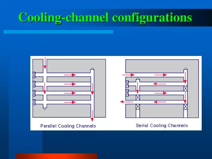

Cooling-channel configurations
E N D
Presentation Transcript
Residual flow stresses due to frozen-in molecular orientation
Thermal-induced residual stress caused by unbalanced cooling
Differential shrinkage for both unfilled and filled materials
Larger volumetric shrinkage due to the high crystallization level
长流道要求高压力 观察报告: 流动长度与零件长度一样。 问题: 加长流动长度一般需要加大注射压力来填充零件。 熔体前沿以不同的速度流动 观察报告: 在恒定的填充速度下,熔体前沿的速度(MFV)随时间变化,这与熔体前沿的面积(MFA)有关。 问题: 不同的MFV将引起零件表面分子或者纤维方向不一致,可能引起收缩和翘曲。 设计方案 1 扇形浇口开在一侧,保持恒定的填充速度曲线
中心浇口使流动长度变短 观察报告: 设计的浇口在零件的几何中心。 方案改进: 与设计1相比流动长度的最大值减小了,这样所需的注射压力也减小了。 变化的熔体前沿速度仍存在 问题: 初期的放射形的填充形式会残留下来,这是不希望 看 到的。 设计方案 2 设计修改:中心浇口
取可变的填充速度曲线,获得恒定的熔化前沿速度取可变的填充速度曲线,获得恒定的熔化前沿速度 方案改进: 使用CAE分析软件所建议的最佳填充速度曲线可以消除MFV的变化。 设计方案 3 设计修改:取理想的填充速度曲线
恒定的熔体前沿速度 观察报告: 熔体前沿的推进在轮廓间的距离恒定,这表明MFV恒定。 最佳填充时间 方案改进: 通过注射时间扫描找到最加填充时间范围,以使注射压力最小。 设计方案 4 可变的填充速度曲线
太高的注射压力 观察报告: 如果所需压力超过机器的最大压力,那么必须改变工艺条件或者设计方案。 比较供选的工艺方案 反复迭代设计: 分析比较可选方案的熔体和模壁的温度﹑浇口和流道的设计或零件的厚度,反复比较所有的方案,选择最佳方案。 设计方案 4 (续)
改变浇口设计 方案改进: 如果注射压力一直很高,那么可以考虑使用多浇口来减小流动长度。这样将会减少所需的注射压力。 再次使用CAE软件可以很快确定正确的浇口位置和最佳填充速度曲线。 设计方案 5 设计修改:改变浇口设计
更低的注射压力和更短的流动长度 方案改进: 用多个浇口可使流动长度显著减小,以便减小所需注射压力。 如果要减小流体废料和进一步减小在流道中的压力损失,可以考虑使用热流道系统。 多个浇口将会导致熔接缝 问题: 多浇口系统的主要缺陷是熔接缝。CAE分析软件可以预测熔接缝位置。 如果熔接缝的位置是不可接受的,那么就必须修改设计(如改变浇口的位置或尺寸)。 设计方案 6 设计修改:三浇口,热浇注系统
最初只有中心浇口的电子阀打开 方案改进: 将电子阀顺序打开可以在保持多浇口的同时消除熔接缝。 当熔体到达时候,下面的浇口再打开 在熔体到来之前,下面的浇口一直关闭。当熔体到达时浇口才打开。 设计方案 7 设计修改:电子阀浇口,实现浇口连续的打开和关闭的控制
熔体温度分布 方案改进: 由CAE显示的熔体温度分布说明了在填充的过程中零件不同位置温度随时间的变化。 模壁的剪切力分布 进一步改进: 当最大剪切力超过一定的水平时,熔体的破裂和空间的不稳定性就会发生。CAE所显示的模壁剪切压力分布可精确的指出潜在的问题。 设计方案 7 (续)