Download
1 / 18
180 likes | 330 Views
The First Free-Vibration Mode of a Heat Exchanger Lid. Thad Hendricks ME 450, Fall 2000 Professor: Dr. Craig Weeks. Introduction. Thad Hendricks worked at: Stewart-Warner South Wind Design and Test Heat Exchangers Lab Technician-Heat Transfer Lab

E N D
The First Free-Vibration Mode of a Heat Exchanger Lid Thad Hendricks ME 450, Fall 2000 Professor: Dr. Craig Weeks
Introduction • Thad Hendricks worked at: • Stewart-Warner South Wind • Design and Test Heat Exchangers • Lab Technician-Heat Transfer Lab • Purpose 1: To find the first mode of a lid for a test unit. • Purpose 2: To prove practicality of ANSYS.
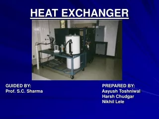
Test Unit Background • This unit is used on 94 inch turbofan engine developed by Pratt-Whitney • Hot air inlet,air is picked up between compressors and turbines: 260 psig at 1100 degrees F(22 pounds per min). • Bleed air outlet: 250 psig at 500 degrees F. This high pressure air is used to cool bearings along the main shaft of the engine. • Stainless tube bundle type heat exchanger.
Test Unit Background • Cooling air inlet, cooling air is picked up from fan bypass: 225 degrees F(90 pounds per min). • Cooling air outlet: at 400 degrees F.
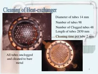
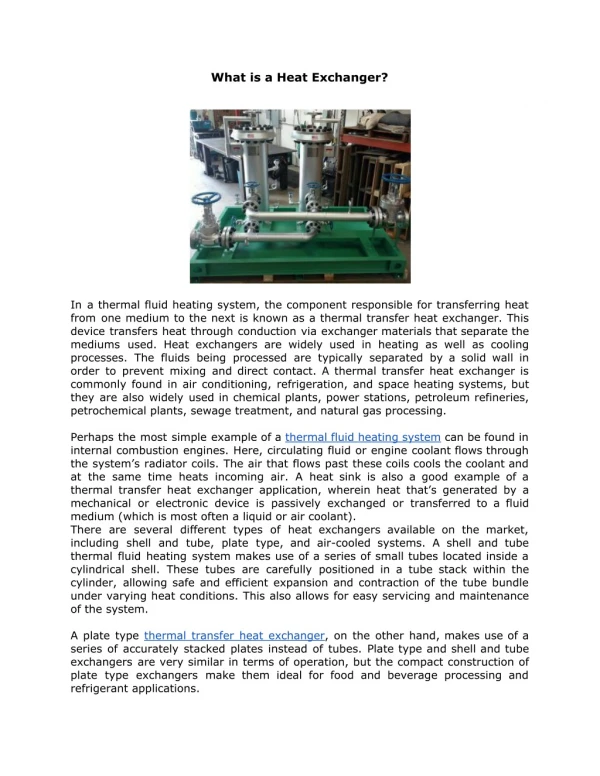
Test Unit Background • Picture of Lid • Lid Functions: Forces air through heat exchanger core with little disturbance to the bypass air. • Made from Stainless Steel(316), properties change little over operation temperature range(100-450F). • E = 28000000 psi, weight density = .29 lb per cubic in.
Mode Theory • Modes occur at certain frequencies • At these frequencies, input amplitude is much smaller than the output amplitude of the object. • The frequency depends on geometry, Modulus of elasticity, density, and constraints. • The first mode has the highest amplitude. • If the first mode occurs out of your operating frequency range, it can be ignored. • This fact makes knowledge of the frequency of the first mode important.
A Simple Example • I started with a beam, fixed at one end. • For a beam it can be shown that where E is modulus, I is moment of inertia, rho is density, A is area, L is beam length, and beta is a constant. For the first and second modes beta equals 3.51 and 22.03 respectively. • For a aluminum beam, Length=10in, Base=1in,Height=.5in, the first mode was calculated to be 160.16 Hz, and second mode was calculated to be 1005 Hz
Beam analyzed in ANSYS • On this slide, the results and picture of the beam mesh are shown. • Brick type elements were used. • The beam was made up of 343 total elements. • The subspace modal extraction method was used. • Three modes were extracted and expanded. • All degrees of freedom were constrained at the end of the beam. • The percent error was 1.3 percent for the first mode and 4.96 percent for the second mode. • It should be noted that the calculations for the beam were made only for the y direction of vibration. The second mode listed in the ANSYS results is for the first mode in the x direction(second mode total). • These results show that the methodology used for solving modal problems on ANSYS was correct.
Beam StressesFirst and Second Modes • It is important to know where the stress concentrations will occur when a body goes into resonance. These spots are where fatigue failure will likely occur. • Plots are Vonmises stress.
Experimental Lab Results • The heat exchanger was mounted on a shaker table. The lid of the heat exchanger had one accelerometer mounted on the center.The shaker had a input acceleration of 2g. The graph shown below shows the output acceleration of the lid with a input acceleration of 2g. The frequency sweep went from 20 to 2000 Hz. This test was specifically run to find the resonance of the lid. As you can see, the first peak during the test occurred between 185 and 200 Hz. This peak shows the first mode of the lid. You can see other peaks after the first. These could possibly be other modes of the lid, or they can be other parts of the heat exchanger reaching their resonance frequencies.
ANSYS Modeling • Shells of type Shell63 Were used. • Some of the areas were free meshed due their complex shapes. • Two of the areas could not be matched to the others because of problems with the drawing, which was obtained from Stewart-Warner(shown on next slide). • Constant thickness was assumed for the top portion of the lid. Also, the flanges and radii were assumed to have a constant thickness. • Again the subspace analysis type was used. • The constraints on the model were all of the degrees of freedom. These were applied at the bolt holes on the right flange. The drawing did not include bolt holes on the left flange, so nodes that approximated the location of the bolt holes on the actual unit were used. • One mode was extracted and expanded. • The model was made of 770 elements.
ANSYS Results • The experimental results matched the ANSYS results. This shows the practicality of ANSYS for this type of analysis.
ANSYS Results • Pictures of Stress Concentrations for experiment versus ANSYS. • The unit was cracked during a resonance dwell test. The input acceleration was a constant 20g . It cracked after approximately 3 hours at the resonance frequency. • Plot is stress in y-direction. The radius is compressed.
Conclusions • ANSYS is useful for this type of analysis • Possible problems can be detected before tooling of the design. • The only change in the design of the unit was the use of Inconel(718) instead of stainless because of its fatigue life.