Download
1 / 26
290 likes | 806 Views
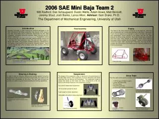
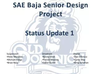
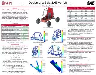
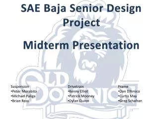
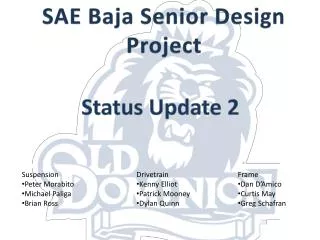
SAE Baja Senior Design Project. Final Presentation. Suspension Peter Morabito Michael Paliga Brian Ross. Drivetrain Kenny Elliot Patrick Mooney Dylan Quinn. Frame Dan D’Amico Curtis May Greg Schafran. Introduction. Objective:. To design a vehicle for the SAE Baja Competition.

E N D
SAE Baja Senior Design Project Final Presentation • Suspension • Peter Morabito • Michael Paliga • Brian Ross • Drivetrain • Kenny Elliot • Patrick Mooney • Dylan Quinn • Frame • Dan D’Amico • Curtis May • Greg Schafran
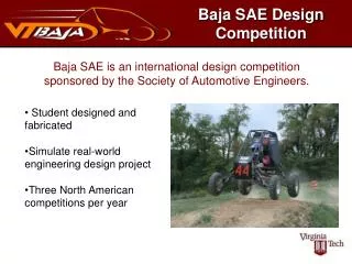
Introduction Objective: To design a vehicle for the SAE Baja Competition Competition Events Acceleration Hill Climb Mud Bog Endurance Maneuverability
Drivetrain Goals: • Accomplish 8:1 Gear Ratio through the gearbox • Create the smallest and lightest gearbox possible • Extra design considerations includes machinability • cost, ease of maintenance
Drivetrain: Calculations Hand Calculations were completed for the Lewis Bending stresses, Barth Velocity Stress, and AGMA gear stresses Solidworks FEA was used to model the expected maximum stress and maximum displacement
Gear Design- Methods Our calculations were based on methods found in Shigley’s Design manual. Gear Ratio Calculations [Veh. wt]*[Sin(incline angle)] = Repelling Weight [650 lbs]*[Sin(40 degrees)] = 418 lbs Rep wt = (tire rad)*(CVT ratio)*(engine tq)*(X min) 418 lbs = (1.0 ft)*(3.85)*(14 lb-ft)*(X min) ----->Xmin= 7.7551 After determining the specific gear selections we also analyzed each gear for: • Minimum Face Width • Interference • Lewis Bending Stress • AGMA Stress and Strength • Barth Velocity Factor • Basic FEA in Solidworks
Gear Design- Results Two Stage Reduction Gearbox (8.0:1) Stage 2 - 4.0:1 Size: 20/80 teeth Pitch: 12 Face Width: 1.5 in Stage 1 - 2.0:1 Size: 20/40 teeth Pitch: 12 Face Width: 1.0 in Gear Ratio: A minimum ratio of 7.7551 was Calculated. We chose 8.0:1, a SF or 1.277 Max torque at wheels: 446 lb-ft Top Speed: 35.7 MPH at 3600 RPM. Gear Material: AISI 4130 Minimum Safety Factor of 1.89 6.5 inch diameter output gear allows room for differential mounting to increase vehicle handling.
Drivetrain: Materials, Weight • ANSI 4130 Steel was chosen for the gear material • because of high yield strength and the • and because of surface properties in reducing fatigue • Case material chosen was 6061 Aluminum Alloy for • Ease of machining and its weight properties • Total Conservative weight estimate is 40 lbs
Drivetrain: Mounting and Simulation Hinge style mount Simulation:
Suspension- Overview • Front Suspension • Basic Double A-arm setup • Same overall design as previous years car • No significant changes, just modifying to fit newly designed frame • Rear Suspension • Using a rear trailing arm set up similar to the 2012 car • Eliminating the dynamic toe aspect, but maintaining the dynamic camber • Improving wheel travel and reliability
Suspension-Optimum K Model REAR FRONT ASSEMBLY
Suspension- Optimum K Output • Steering wheel angle vs. steering angle (front left) • Motion is of a body roll
Suspension- Optimum K Output • Camber angle (rear right) • Motion is of a body roll
Suspension- Optimum K Output • Camber Angle (rear right) • Motion is of a jump
Suspension- Optimum K Output • Camber angle (front right) • Motion is of a jump
Suspension- Geometry FEA - Stress TRAILING ARM FEA - Displacement 1’’ X 0.065’’ 4130 STEEL
Suspension- Geometry FEA - Stress UPPER A-ARM 1’’ X 0.065’’ 4130 STEEL FEA - Displacement
Suspension- Geometry FEA - Stress LOWER A-ARM FEA - Displacement 1’’ X 0.065’’ 4130 STEEL
Suspension- Shock Selection • Fox Float Racing Shocks: • Adjustable air spring, velocity damping control, and light weight. • Reduced Cost - $521.25 per pair versus $859 per pair for Custom Works Shocks. • Comparable performance
Frame- Methods • SAE standards • Firewall • Front end • Roll cage • Rear end • Finite Element Analysis
Frame- Analysis • The 2012 ODU Mini Baja (55th place) weighed 479 pounds • Cornell’s car (3rd place) weighed only 306 pounds • Reduce frame size and weight • Eliminate redundant members
Frame-Results Material-4130 steel tubing: primary members: 1.25”x.065 secondary members: 1”x.065 Shorter overall length Lighter than previous ODU cars: 63.7 lbs.