Download
1 / 11
110 likes | 126 Views
MAROC is a 64-channel MAPMT chip for ATLAS Lumi with advanced features like variable gain, high sensitivity, low crosstalk, and more. MAROC1 & MAROC2 layouts and features are detailed.

E N D
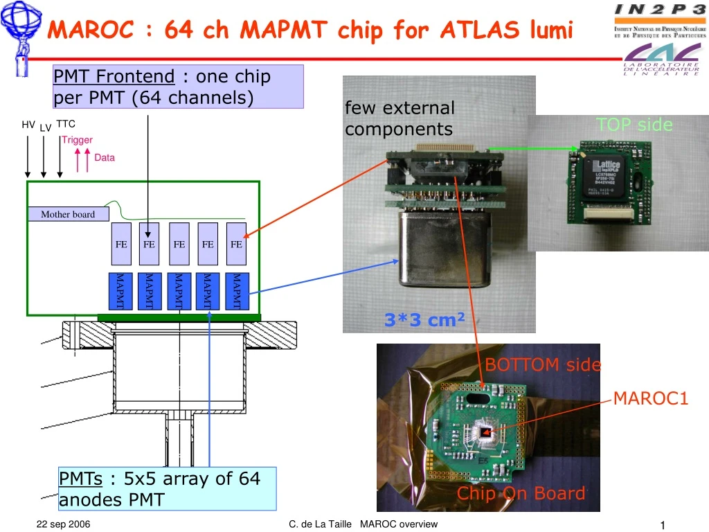
MAPMT MAPMT MAPMT MAPMT MAPMT MAROC : 64 ch MAPMT chip for ATLAS lumi PMT Frontend : one chip per PMT (64 channels) few external components TOP side TTC HV LV Trigger Data Mother board FE FE FE FE FE 3*3 cm2 BOTTOM side MAROC1 PMTs : 5x5 array of 64 anodes PMT Chip On Board C. de La Taille MAROC overview
MAROC : 64 ch MAPMT chip for ATLAS lumi • Characteristics • 64 PMT channels input (50-100 Ω) • Variable gain current conveyor (0-2) 6 bits : 2, 1, 1/2, 1/4, 1/8, 1/16 linearity : 1% • 64 discriminator outputs (GTL) • 100% sensitivity to 1/3 photoelectron (50fC). Counting rate up to 2 MHz • Common threshold loaded by internal 10bit DAC • 1 multiplexed charge output with variable shaping 20-200ns and Track & Hold. • Dynamic range : 11 bits (2fC - 5 pC) • Crosstalk < 1% • Technology : AMS SiGe 0.35µm • Submitted 13 june 05 Area 12 mm2 • Dissipation 130 mW @ VDD=3.5V Hold signal Multiplexed Variable Slow Shaper S&H charge output 64 PM inputs Variable Gain Preamp. Bipolar Fast Shaper 64 Tri g ger outputs 10 bit DAC discriminator threshold 10 bits DAC Gain correction 6 bits/channel Synoptic diagramm of MAROC chip layout of MAROC chip C. de La Taille MAROC overview
MAROC1 : Efficiency curves 0 fC 100fC Trigger efficiency for different premap gains : (0.5 to 4) Trigger efficiency curves 50 fC 5 pC 50% efficiency for the 64 channles Crosstalk <1% C. de La Taille MAROC overview
MAROC1: SLOW SHAPER Analog output Slow shaper waveforms for various gain settings (0 to 4) Slow shaper waveforms for Qin=0 to 6pC Linearity of gain setting (0 to 4). Linearity 0 to 6pC. Noise = 500uV C. de La Taille MAROC overview
GPIB port USB port 64ch PM socket MAROC (COB) Control Altera TEST BOARD C. de La Taille MAROC overview
MAROC2 architecture • MAROC2 = MAROC1 + additionnal features (WILKINSON ADC, 3 discriminators, Encoder) Hold signal Multiplexed Analog charge output Variable Slow Shaper 20-100 ns S&H S&H 64 Wilkinson 12 bit ADC Photons Multiplexed Digital charge output 64 inputs Variable Gain Preamp. Bipolar Fast Shaper Photomultiplier 64 channels 64 trigger outputs (to FPGA) 80 MHz encoder Unipolar Fast Shaper Gain correction 64*6bits 3 DACs 12 bits 3 discri thresholds (3*12 bits) LUCID C. de La Taille MAROC overview
MAROC2 layout • Technology : AMS SiGe 0.35µm • Submitted March 06 • Area 16 mm2 • Received in june 06 • 240 pins Control signals and power supplies 3 discris 64 digital outputs 64 Analog Channels 64 ch Wilkinson 12bit ADC Triple 12bit DAC Control signals and power supplies C. de La Taille MAROC overview
Efficiency curves: MAROC2 • Threshold : 22 fC • Dispersion : +/- 1.6 fC • Noise : ~ 2 fC C. de La Taille MAROC overview
Wilkinson ADC results ADC count vs Vin INL (ADC count) vs Vin +1.5 -1.5 Vref shaper
WR S R A M 128 * 160 HaRDROC architecture : readout of ILC DHCAL RPCs • Full power pulsing • Digital memory: Data saved during bunch train. Only one serial output • Store all channels and BCID for every hit. Depth = 128 bits • Data format : 128(depth)*[2bit*64ch+32bit(bcid)+8bit(Header] = 20kbits • Sequential readout @ 10 MHz : 20k* 100 ns = 2 µs (read up to 100 chips/inter bunch) Hold: Ext signal or OR output Multiplexed Analog charge output Variable Slow Shaper 20-100 ns S&H Variable Gain Preamp. trig1<0> 64 INPUTS Bipolar Fast Shaper OR Latch Vth1 - trig1<63> trig0<0> Gain correction 64*6bits G=0 to 4 Latch Vth0 - trig0<63> 1 OUTPUT Transfered to DAQ during Inter-bunch 2 DACs 10 bits -Vth1 2 discri thresholds (2*10 bits) trig1<0> -Vth0 trig1<63> 32 bit counter BCID C. de La Taille MAROC overview
HaRDROC layout • Technology : AMS SiGe 0.35µm • Submitted sept 06 • Area 16 mm2 • 180 pins • 100 mW Control signals and power supplies 2 discris 128*128 Digital memory 64 Analog Channels Dual DAC Bandgap Control signals and power supplies C. de La Taille MAROC overview