Download
1 / 47
540 likes | 741 Views
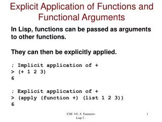
Functions and Functional Blocks. COE 202 Digital Logic Design Dr. Aiman El-Maleh College of Computer Sciences and Engineering King Fahd University of Petroleum and Minerals. Outline. Enabling function Decoders Implementing Functions using Decoders Encoders Multiplexers

E N D
Functions and Functional Blocks COE 202 Digital Logic Design Dr. Aiman El-Maleh College of Computer Sciences and Engineering King Fahd University of Petroleum and Minerals
Outline • Enabling function • Decoders • Implementing Functions using Decoders • Encoders • Multiplexers • Implementing Functions using Multiplexers • DeMultiplexers • Design Examples using MSI Functional Blocks
Functions and Functional Blocks • Will consider functions that are useful in designing other combinational and sequential circuits • Such circuits can be implemented using a set of functional blocks • In the past, many functional blocks were implemented as separate SSI (small scale integration), MSI, and LSI integrated circuits (ICs) • Today, they are often used as parts in a design library for use within larger VLSI circuits 10s 100s 1000s millions gates/chip SS MS LS VLS (Small Scale) (Medium Scale) (Large Scale) (Very Large Scale)
Enabling Function • Enable: Allow an input signal to pass through to an output • Disable: block an input signal from passing through to an output, replacing it with a fixed state (1, 0, or HiZ) • Disable: EN = 0 in both cases • When disabled, output = 0 • When disabled, output = 1
Decoders • A decoder is a circuit that decodes an input code. Given a binary code of n-bits, a decoder will tell which code is this out of the 2n possible codes. • A decoder may have enable line • In general, output i equals 1 if and only if the input binary code has a value of i. • Thus, each output line equals 1 at only one input combination but is equal to 0 at all other combinations. • Thus, the decoder generates all of the 2nmintermsof n input variables.
2-to-4 Decoder • A 2-to-4 decoder contains two inputs denoted by A1 and A0 and four outputs denoted by D0, D1, D2, and D3. • For each input combination, one output line is activated, that is, the output line corresponding to the input combination becomes 1, while other lines remain inactive. • For example, an input of 00 at the input will activate line D0. 01 at the input will activate line D1, and so on.
2-to-4 Decoder • Notice that, each output of the decoder is actually a minterm resulting from a certain combination of the inputs, that is: ( minterm m0) ( minterm m1) ( minterm m2) ( minterm m3)
2-to-4 Decoder with Enable • Attach m output-enabling gates opened by the EN input • Note use of X’s to denote both 0 and 1 at the inputs • Combination containing two X’s represent four input binary combinations
3-to-8 Decoder • In a three to eight decoder, there are three inputs and eight outputs, A0 is the least significant variable, while A2 is the most significant variable. • Each output represents one minterm • For example, for input combination A2A1A0 = 001, output line D1 equals 1 while all other output lines equal 0’s • It should be noted that at any given instance of time, one and only one output line can be activated.
3-to-8 Decoder Implementation Notice that each output line is the minterm corresponding to the input code, i.e. D5 is m5
Decoder Expansion • Example: 3-to-8 from two 2-to-4 with EN • Using two 2-to-4 decoders & one 1-to-2 decoder
Implementing Functions using Decoders • Implementing functions of n inputs and m requires: • Specification: As a Truth Table (has n input columns and m output columns)or m sum of minterms (SOm) expressions • Implementation requires: One n-to-2n-line decoder m OR gates, one for each output • Procedure: From the truth table: For each ‘1’ in the truth table of an output, connect the corresponding Di of the decoder to the OR of that output From the m minterm expressions: Connect the decoder Di’s corresponding to the minterms of each output to the OR of that output
Implementing Functions using Decoders • Example:1-bit adder (Full Adder) • We need: • 2 SOm expressions • 3-to-23 Decoder • 2 OR gates of appropriate # of inputs Larger # of 1’s require larger ORs. If so, Consider expressing F and using a NOR instead! LSB
Encoders • An encoder performs the inverse operation of a decoder. • It has 2n inputs, and n output lines. • Only one input can be logic 1 at any given time (active input). All other inputs must be 0’s. • Output lines generate the binary code corresponding to the active input.
Octal-to-Binary Encoder Assuming only 1 (and at least 1) Input line being active at a time Only 8 rows are relevant, out of the 2^8 = 256 rows
Octal-to-Binary Encoder • Note that not all input combinations are valid. • Valid combinations are those which have exactly one input equal to logic 1 while all other inputs are logic 0’s. • Since, the number of inputs = 8, K-maps cannot be used to derive the output Boolean expressions. The encoder implementation, however, can be directly derived from the truth table: • Since A0 = 1 if the input octal digit is 1 or 3 or 5 or 7, then we can write: A0 = E1 + E3 + E5+ E7 • Likewise, A1 = E2 + E3 + E6+ E7, and similarly • A2 = E4 + E5 + E6+ E7 • Thus, the encoder can be implemented using three 4- input OR gates.
Major Limitation of Encoders • Exactly one input must be active at any given time. • If the number of active inputs is less than one or more than one, the output will be incorrect. • For example, if E3 = E6 = 1, the output of the encoder A2A1A0 = 111, which implies incorrect output. • Two Problems to Resolve: • 1. If two or more inputs are active at the same time, what should the output be? • 2. An output of all 0's is generated in 2 cases: • when all inputs are 0 • when E0 is equal to 1. How can this ambiguity be resolved?
Major Limitation of Encoders • Solution To Problem 1: • Use a Priority Encoder which produces the output corresponding to the input with higher priority. • Inputs are assigned priorities according to their subscript value; e.g. higher subscript inputs are assigned higher priority. • In the previous example, if E3 = E6 = 1, the output corresponding to E6 will be produced (A2A1A0 = 110) since E6 has higher priority than E3. • Solution To Problem 2: • Provide one more output signal V to indicate validity of input data. • V = 0 if none of the inputs equals 1, otherwise it is 1
4-to-2 Priority Encoders • Sixteen input combinations. • Three output variables A1, A0, and V. • V is needed to take care of situation when all inputs are equal to zero.
Multiplexers: 2n-to-1 • A multiplexer (MUX) selects information from one of 2n input line and directs it toward a single output line. • A typical multiplexer has: • 2n information inputs (I(2n – 1), … I0) (to select from) • 1 Output Y (to select to) • n select control (address) inputs (Sn - 1, … S0) (to select with) • Implemented using decoders • MUX selection circuits can be duplicatedm times (with the same selection controls in parallel) to provide m-wide data widths
2-to-1 MUX • The single selection variable S has two values: • S = 0 selects input I0 • S = 1 selects input I1 • 3-input K-map optimization gives the output equation: • The circuit: • Can be seen As: 1-to-2 decoder + Enabling + Selection Truth Table 2nMinterms 2n I Inputs
4-to-1 MUX • Using 2-to-4 decoder +4 2-input AND + 4-input OR for Enabling/Selection # of the ANDs 2-to-4 Size of the Select Inputs = Log2 (4) X
4-to-1 MUX • A 4-to-1 MUX can be implemented using three 2-to-1 MUXs. • F = s1’s0’ I0 + s1’s0 I1 + s1s0’ I2 + s1s0 I3 = s1’ (s0’ I0 + s0 I1)+ s1 (s0’ I2 + s0 I3) 2x1 MUX I0 I1 2x1 MUX F S0 2x1 MUX I2 S1 I3 S0
Quad 2-to-1 MUX • Given two 4-bit numbers A and B, design a multiplexer that selects one of these 2 numbers based on some select signal S. Obviously, the output (Y) is a 4-bit number. • The 4-bit output number Y is defined as follows: • Y = A IF S=0, otherwise Y = B • The circuit is implemented using four 2x1 Muxes, where the output of each of the Muxes gives one of the outputs (Yi).
Quad 2-to-1 MUX A0 2x1 MUX Y0 B0 S A1 2x1 MUX Y1 B1 S A2 2x1 MUX Y2 B2 S A3 2x1 MUX Y3 B3 S
Implementing Functions using Multiplexers • Implementing a function of n inputs and m outputs (n to m) requires: • Truth table, or m Sum-of-minterms expressions • m-wide 2n-to-1 multiplexer • Design: • In the order they appear in the truth table: • Apply the function inputs to the multiplexer select inputs Sn -1, … , S0 • Label the outputs of the multiplexer with the output variables • Value-fix the information inputs to the multiplexer using the values from the truth table. For don’t cares, use either 0 or 1.
Implementing Functions using Multiplexers • Example: 1-bit adder
Implementing Functions using Multiplexers • Example: 1-bit adder, a more efficient approach
Implementing Functions using Multiplexers • Example: F (A,B,C,D) = m(1,3,4,11,12,13,14,15) • 16 rows in truth table 16-to-1 MUX (conventional approach) • But using the efficient approach … will use only an 8-to-1 MUX + 1 inverter
Implementing Functions using Multiplexers • Example: F (A,B,C) = m(1,2,6,7)
Shannon's Expansion • The cofactor of f(x1,x2,…,xi,…,xn) with respect to variable xi is fxi= f(x1,x2,…,xi=1,…,xn) • The cofactor of f(x1,x2,…,xi,…,xn) with respect to variable xi’ is fxi’= f(x1,x2,…,xi=0,…,xn) • Theorem: Shannon's Expansion • Any function can be expressed as sum of products (product of sums) of n literals, minterms (maxterms), by recursive expansion.
Shannon's Expansion • Example: f = ab + ac + bc • fa = b + c • fa’ = bc • F = a fa + a’ fa’ = a (b + c) + a’ (bc) • Using Shanon’s Expansion we can implement any function using any sizes of multiplexers • 2x1 MUX: f = a [ b (1) + b’ (c) ] + a’ [ b (c) + b’ (0) ] • Three 2x1 Muxs • 4x1 MUX: f = a b (1) + a b’ (c) + a’ b ( c) + a’ b’ (0)
Demultiplexer Many-to-One One-to-Many De MUX MUX Demultiplexer Multiplexer A device that moves data arriving on a single input (E) to one of m outputs (Ds) Determined by the value of log2 address inputs (As) A decoder with Enable is Referred to as: Decoder/Demultiplexer DeMUX
Decoder with Enable = DeMultiplexer • Alternatively, can be viewed as distributing the value of the signal EN to 1 of 4 outputs • In this case, called aDemultiplexer Data Input Outputs Address No 1’s Decoder is disabled Normal Decoder Operation
Design Examples using MSI Functional Blocks • 1. Adding Three 4-bit numbers • 2. Adding two 16-bit numbers using 4-bit adders • 3. Building 4-to-16 Decoders using 2-to-4 Decoders with Enable • 4. Selecting the larger of two 4-bit numbers • 5. BCD to Excess-3 Code Converter using a decoder and straight binary encoder
Adding Three 4-bit Numbers • Problem: Add three 4-bit numbers (X, Y, Z) using standard MSI combinational components • Solution: Let the numbers be X3X2X1X0, Y3Y2Y1Y0, Z3Z2Z1Z0 X3X2X1X0 + Y3Y2Y1Y0 ------------------- C4 S3S2S1S0 S3S2S1S0 + Z3Z2Z1Z0 ------------------- D4 F3F2F1F0 Note: C4 and D4are generated in position 4. They must be added to generate the most significant bits of the result
Adding Three 4-bit Numbers 64 59 + 123 89 + 212 1
Adding Two 16-bit Numbers using 4-bit Adders • Solution: Four 4-bit adder blocks are connected in cascade, with carries rippling in between
Design a 4-to-16 Decoder Using 2-to-4 Decoders with Enable • Problem: Design a 4x16 Decoder using 2x4 Decoders • Solution: Each group combination holds a unique value for A3A2 • One Decoder can be therefore used with inputs: A3A2 • Four more decoders are needed for representing each individual color combination Select 1 of the 4 2-to-4 decoders Common to all 4 3-to-4 decoders A3A2 = 00 A3A2 = 01 A3A2 = 10 A3A2 = 11
Design a 4-to-16 Decoder Using 2-to-4 Decoders with Enable D0D1D2D3 D12D13D14D15 D8D9D10D11 D4D5D6D7 A0A1 A0A1 A0A1 A0A1 2x4Decoder 2x4Decoder 2x4Decoder 2x4Decoder E D0D1D2D3 A2A3 2x4Decoder Enable for the full 4-to16 decoder E
Hardware that Compares Two Unsigned 4-bit Numbers and Passes the Larger of the Two • Solution: We will use a magnitude comparator and a Quad 2-to-1 MUX. How?
BCD to Excess-3 Code Converter using a Decoder and Straight Binary Encoder Excess-3 BCD Index 0 1 2 3 4 5 6 7 8 9 BCD: 0 - 9 Excess-3: 3 - 12