Database Systems Development
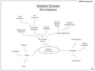
Database Systems Development. View Integration. View Modelling. Physical Database Design. Database Implementation. Logical Modelling. Conceptual Modelling. Requirements Elicitation. Physical Modelling. E-R Modelling. Development Process. Object Modelling. Methods.

Database Systems Development
E N D
Presentation Transcript
Database SystemsDevelopment View Integration View Modelling Physical Database Design Database Implementation Logical Modelling Conceptual Modelling Requirements Elicitation Physical Modelling E-R Modelling Development Process Object Modelling Methods Database Development Techniques Techniques Toolkit Normalisation Tools
Development Process Database Systems Development Conceptual Modelling User Requirements Elicitation Business Area Business Area View Modelling View Modelling Conceptual Modelling View Integration Logical Modelling Database System User Physical Modelling Data Administration Physical Modelling Process Strategic Data Planning Physical Design Database Development Database System Database Implementation User Database System Database Administration
Information Systems Development Clients Costs Benefits Constraints Requirements Resources Information Systems Development Changes Systems Conception Systems Maintenance Business Case IS Systems Analysis Systems Implementation Requirements Specification Users IS Users HAS Requirements IS Systems Design Systems Construction System Design System Configuration Development Information System
Database Development Process Database Systems Development User Requirements Specification Requirements Elicitation Requirements Conceptual Model Conceptual Modelling Logical Model Logical Modelling Physical Model User Database System Physical Modelling Database System Documentation
Conceptual Modelling Process Conceptual Modelling Process Business Area Business Area View Modelling View Modelling Requirements Requirements Business Area Conceptual Model Business Area Conceptual Model View Integration Global Conceptual Model Logical Modelling
Physical Modelling Process IS Development Volume & Usage Analysis Physical Modelling Process Logical Model Logical Modelling Physical Design Physical Design User Database System Database Implementation
Key Phase Sub-Phase Activities Alternative Activity Requirements analysis Conceptual modelling View Modelling Defining entities/objects Defining relationships and constraints on relationships Defining attributes Defining abstraction mechanisms Defining behaviour View Integration Identifying communalities amongst views Producing a global conceptual model Accommodating the conceptual model to a relational schema Key Activities – Conceptual Modelling
Logical modelling Normalisation Producing a 3NF schema through non-loss decomposition Producing a 3NF schema through a dependency analysis Reconciling the normalised schema with the schema produced from conceptual modelling Key Activities – Logical Modelling
Physical modelling Physical Database Design Volume Analysis Usage/transaction analysis Integrity Analysis Control/Security Analysis Distribution Analysis Database Implementation Selecting the DBMS Creating the Physical Schema Establishing storage structures and associated access mechanisms Adding indexes De-normalisation Defining users and privileges Tuning in terms of the chosen DBMS Building integrity contraints Key Activities – Physical Modelling
Link between Database and IS Development Life-Cycle Requirements Analysis Systems Analysis Systems Design Implementation real world database system requirements Elicitation conceptual modelling logical modelling physical modelling
Context for Database Development Data Administration Strategic Data Planning Corporate Data Model Database Development Database System Database Administration
Database Development Toolkit Methods Techniques Tools
Summary – Database Development • Systems development of whatever form consists of a development process and an associated development toolkit • A development process consists of a series of activities for producing an ICT system. • A development toolkit consists of methods, techniques and tools. • The database development process is divided into four main stages: requirements elicitation, conceptual modelling, logical modelling and physical modelling. • Requirements elicitation involves establishing the key technical requirements for a database system usually through formal and informal interaction between developers and users. • Conceptual modelling involves building a model of the real world expressed in terms of the data requirements established. • Logical modelling involves constructing a model of the real world expressed in terms of the principles of some data model. • Physical modelling involves constructing a model of the real world expressed in terms of data structures and access mechanisms available in a chosen DBMS. • The database development toolkit consists of methods, techniques and tools.
RequirementsElicitation Requirements Specification Interviews Requirements Elicitation Observation Elicitation Techniques Documentary Analysis Workshops Ethnography Stakeholder Identification Prototyping
Stakeholders Client End-User Customer Regulator
Requirement Characteristics Vary with stakeholder group Conflict Freezing
Elicitation and Capture Requirements Elicitation Requirements Capture Client Reality User Producer Producer Customer Regulator
Requirements Specification as Modelling Constructs Modelling Notation Model Principles
Requirements Elicitation Techniques Requirements Elicitation Interviews Observation Ethnography Prototyping Workshops
Summary – Requirements Elicitation • · Systems analysis involves two primary and inter-related activities - requirements elicitation and requirements representation. • · Requirements elicitation is that process devoted to the identification of requirements. • · Requirements specification is that process concerned with the representation of requirements. • · A requirement is any desired feature of an information technology system. • · Requirements may vary depending on the stakeholder group. Requirements are not objective phenomena. Requirements elicitation involves attempting to achieve some inter-subjective agreement amongst stakeholder groups about requirements. • · Requirements are likely to change over time. Part of the reason for adaptation of systems is because requirements change. • · Requirements must be frozen at some point in order to construct an information technology system - an artefact. • · Conceptual modelling is still subject to the important philosophical characteristics of organisational reality.
E-R Diagramming 1:1 1:M Cardinality Relationship Attribute Entity Entity M:N Notation Mandatory Principles Optionality Entity Optional Relationship Inclusivity/ Exclusivity Recursive Relationships Constructs Ternary Relationships Attribute Roles Accommodation Chasm Trap Pragmatics View Integration View Modelling Connection Traps Fan Trap Modelling Time
Constructs – Entity Model Constructs Entity Relationship Attribute
Variation in E-R Diagramming Notation Course Module Course Module 1 M Course Module Course Module 1:1 0:M Course Module
E-R Notation Entities Course Module Student Relationships r1 Course Module r2 Module Student Attributes moduleName Level studentDOB studentName Module Student
Cardinality and Optionality Cardinality A Customer Customer Customer BankAccount BankAccount BankAccount Optionality B Customer Customer BankAccount BankAccount
A 1:M relationship as an Instance Diagram Computer Studies 234 237 Mechanical Engineering 123 Employs Lecturer Business Studies Department
A M:N relationship as an Instance Diagram Lecturer 34698 234 37798 237 34888 345 Counsels 24988
Inclusivity and Exclusivity Exclusivity A Lecturer r1 - teaches, is taught by or r1 r2 r2 - prepares, is prepared by Module Inclusivity B Lecturer r1 - teaches, is taught by and r1 r2 r2 - examines, is examined by Module
Recursive Relationships Module prerequisite
Ternary Relationship Employee skill_used Skill Project
Roles A B orders Employee manages Customer Product is_shipped
Simplifying M:N Relationships A B studentNo studentNo r1.1 Student Student studentNo r1 registration moduleName Module Module r1.2 moduleName broker no
Connection Traps A - Fan Trap Staff Department Faculty Faculty 1 1 1 r1 r2 2 2 Department Staff 3 3 2 4 4 B - Chasm Trap Staff Department Faculty Faculty 1 1 1 r1 2 2 Department 3 3 2 r2 4 4 5 Staff
Faculty Staff Staff Department Faculty Faculty 1 1 1 r1 2 2 r3 Department 3 3 2 4 r2 3 5 Staff
Modelling Time A Course Student r1 courseCode studentNo B Course Student r1.1 r1.2 courseCode StudentNo Enrolment courseCode studentNo enrolmentDate
Accommodating Relational Schema A B courseCode Course Course courseCode r1 r1 Module Module courseCode not null courseCode null Modules(moduleName, courseCode,....) Courses(courseCode, ....)
Two Entity Models A Lecturer Teaches courseName Module B Lecturer Course Teaches Unit
Integrated Entity Model Lecturer Teaches Course Module
Summary - Entity Modelling • E-R diagramming is a top-down approach to data analysis. Originally proposed as a data model, E-R diagramming is now normally used as a conceptual modelling technique. • There are three basic constructs in the E-R data model: entities, relationships and attributes. • An entity may be defined as a thing which the enterprise recognises as being capable of an independent existence and which can be uniquely identified. • A relationship is some association between entities. Relationships are characterised by two sets of rules: cardinality rules and optionality rules. • An entity is characterised by a number of properties or attributes. • A number of extensions have been proposed to the E-R approach: unary and ternary relationships, roles. • There is no agreed notation for representing entity models. A number of graphic notations may be used. An entity model may also be represented in the form of a data dictionary. • Schema modelling (sometimes known as view modelling) is the process of transforming individual user requirements into a conceptual schema (or view). Schema integration (sometimes known as view integration) is the process of combining individual schemas into a global, unified schema which encapsulates the data requirements from all of the input schemas.
ObjectModelling Entity Partial/Covering Sub-classes Association Aggregation Attribute Method() Disjoint/Overlapping Subclasses Generalisation Generalisation M:N Notation Component-Object Principles Member-Collection Aggregation Portion-Mass Association Classification Object Stuff-Object Feature-Activity Place-Area Generalisation Relationship Constructs Aggregation Accommodation Pragmatics Object Model Attribute Composing Object Model Class State Transition Diagram Method
Constructs – Object Model Structural Abstraction Behavioural Abstraction Object Method Object Class Attribute Association Generalisation Aggregation
Object Classes Stock interestRate issueNewStock() changeInterestRate() Share dividend issueNewShare() changeDividend()
Generalisation/Specialisation Object Class Specialisation Generalisation Object Class
Classification/Instantiation Object Class Instantiation Classification Object
Generalisation in Stock Market Model Security (disjoint, complete) Stock Share (disjoint, complete) (disjoint, complete) Debenture VariableStock PreferenceCapital VariableCapital Agent (disjoint, incomplete) FinancialIntermediary Order Investor (disjoint, complete) (overlapping, incomplete) OpenOrder DayOrder Broker MarketMaker (disjoint, complete) (disjoint, complete) OpenSellOrder OpenBuyOrder DaySellOrder DayBuyOrder
Accommodating Generalisation · Create one table. Include all the attributes of the superclass plus all the attributes of each subclass in the table. · Create one table for each subclass. Include all the attributes for the superclass in each subclass table. · Create one table for each subclass and one table for the superclass.
Aggregation/Instantiation Object Class Decomposition Aggregation Object
Aggregation in Stock Market FinancialPortfolio Stock Share InsurancePolicy SavingsAccount
Meronymic Relations Meronymic Relations Component-Object Member-Collection Portion-Mass Stuff-Object Feature-Activity Place-Area
Accommodating Aggregates • · Create one table for each component class • · Create one table for the aggregate class • · Post the primary key from the aggregate into each component