Download

1 / 23
230 likes | 245 Views
Updates on the layout, modules, and software of the HV system for detector chambers at CERN, including testing, repairs, and monitoring procedures. Focus on A876 and A877 modules.

E N D
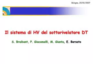
Bologna, 20/01/2007 Il sistema di HV del sottorivelatore DT S. Braibant, P. Giacomelli, M. Giunta, E. Borsato
DT HV electrodes Il sistema di HV delle camere DT
HV layout 1 chamber A876 A877 Inside SY1527 Il sistema di HV delle camere DT
HV layout 1 macrochannel= 1 layer = 4 HV channels Il sistema di HV delle camere DT
Wires0 Wires1 OutputChannels (Set V0, i0…) HV LAYER1 Global HV+ Strips HV PHI1 Cathodes Global HV- LV HV THETA MacroChannels (Set ON/OFF, RuP,…) HV PHI2 >100 m A876 A877 powers 1 DT HV Hardware setup Il sistema di HV delle camere DT
HV layout Il sistema di HV delle camere DT
HV modules • 10 SY1527 (8 used by HV, 1 by LV, 1 spare) • 65 A876 (60 used, 5 spares) • 250+10 A877 (190+10 with 3 connectors, 60 with 2) (240 modules used, 10+10 A877/3 spares) • Apart from 5 A876, all modules have been received at CERN • All modules have been tested Il sistema di HV delle camere DT
HV modules • A876 • 60/60 modules received (77 produced by CAEN) • 3 showed problems and have already been repaired (for 2 of those CAEN did not observe anything wrong) • A877 • With 2 connectors 60/60 received (63 produced by CAEN) • Sent back to CAEN 12, on 7 nothing wrong found, on the remaining 5 some electronics faults were found (active components changed, hv cable disconnected, calibration redone, etc.). Repaired. • With 3 connectors 190/190 received • 35 (!!) have been sent to CAEN to be repaired. On 15 modules nothing wrong found, on the other 20 found electronics problems (active components changed, hv cable disconnected, calibration redone, etc.). Repaired. • Still at CAEN 4 A877 Il sistema di HV delle camere DT
HV slow controls software • Slow controls software is based on the SCADA environment PVSS. • We have the largest slow controls system in operation at CERN with more than 15000 channels to control and monitor. • When all channels will be operated together we will have 6 dedicated PCs to run the software as a distributed environment. • Our slow controls system can be operated as stand alone or connected to the central CMS DCS. Il sistema di HV delle camere DT
DT HV System HV System HV Wheel-2 HV Wheel-1 ………. HV Wheel+2 HV MB1 …….. HV MB4 CUs HV Chamber 1 …….. HV Chamber 14 HV SL 1 HV SL 2 HV SL 3 HV L1 HV L2 HV L3 HV L4 Wires 1 Strips IBeams Wires 0 DUs Il sistema di HV delle camere DT
HV DUs & CUs • 3 types of DUs: • FwCaenChannelWires • FwCaenChannelStrips • FwCaenChannelIBeams • States based on dpe actual.status & actual.vMon • CUs: • HVLayerNode • States: ON, OFF, RAMP_UP, RAMP_DOWN, OVERCURRENT, WARNING, TRIPPED, ERROR, …… • HVSLNode (“Translator” node type) • States: PHYSICS, READY, NOT_READY, WARNING, ERROR, …… • HVGenericNode (for Chamber, Station and Wheel level?) • States: PHYSICS, READY, NOT_READY, WARNING, ERROR, …… Il sistema di HV delle camere DT
FEATURES: • Java ActiveX based User Interface • Reads geometry descriptions from EMDB • Completely interactive • Good for error tracking and correlation • Easy integration into the supervisor FOR DEVELOPERS: • Easy to use from PVSS • Functions providing full control of the detector 3D panels. • Create labels • Create behaviors • Automatically move the view and rotation points. DT Interactive UI (by R. Gomez-Reino Garrido)
Example Il sistema di HV delle camere DT
Included functionalities (I) • Monitoring, settings, FsMs trees,… • Java Interface (R. Gomez-Reino) Il sistema di HV delle camere DT
Included functionalities (II) • Connection to Oracle Configuration Db Il sistema di HV delle camere DT
Included functionalities (III) • Connection to Oracle Condition Db Il sistema di HV delle camere DT
Procedures implemented • Ramp up (single layer) in 4 steps: • 3(1) intermediate state for Wires(Strips and I-Beams) • Ramp down in 2 steps • 1 intermediate state for Wires • Recover from Trip: • Switch off the whole layer; after a delay switch on the layer using the ramp up procedure (check trip frequency, currents,…) • OvC handling: • If OvC on Strips or I-Beams lower Wires voltage by 200 V • A877 boards not current limited; trip condition handled via software (now hardware trip time available too) • Voltage difference check: • Every 20 sec. check of voltage difference btw Strips and Wires; if bigger than 1850 V (i.e. discharge regime), Wires voltage lowered by 200 V • Check communication with power supplies Il sistema di HV delle camere DT
Conclusions • We have all the modules of the HV system in hands at Cern. HV modules test was finished several months ago. • All the A877 modules have been installed in the racks on the balconies • Slow controls software ready and in operation since a long time. • We have observed a relatively high number of faults in the A877 modules. Only a few in the A876 modules. Il sistema di HV delle camere DT
HV modules tests • 4 different tests: • Test 1: Min. voltage, Max. current • Resistive Loads • Test 2: Max. voltage, Max. current • RC loads (same of Test 3) • Test 3: Ramping cycles • RC loads (same of Test 2) • Test 4: Min. voltage, Null current • No loads Il sistema di HV delle camere DT
HV modules tests • “OvC with oscillating Voltage” • Observed during Test 1 in the majority of the newer A877 MB4 boards (no problems during Tests 2&3, where boards used in working range) • Hardware differences between the older A877 standard boards and the newer A877 MB4 boards? YES Some components of the newer boards have a different tolerance: this was causing a slightly different behavior of the channels in their standard working range → a capacitor was added to each channel CAEN assures that board performances in the standard working range is the same for all boards Il sistema di HV delle camere DT
Conclusions • For the magnet test we plan to power a total of 14 DTs in sector 10 of wheel YB+1 and sectors 10 and 11 of wheel YB+2. • The HV system used will be the final one manufactured by CAEN. Also aim at having also final cables, patch panels, etc. • PVSS project with FSM integrated with the central CMS DCS will be available. Il sistema di HV delle camere DT