Download
1 / 23
230 likes | 540 Views
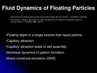
Fluid Dynamics of Floating Particles. Fluid dynamics of floating particles (with experiments by Wang, Bai, and Joseph). J. Fluid Mech. Submitted.

E N D
Fluid Dynamics of Floating Particles Fluid dynamics of floating particles (with experiments by Wang, Bai, and Joseph). J. Fluid Mech. Submitted. D.D. Joseph, J. Wang, R. Bai and H. Hu. 2003. Particle motion in a liquid film rimming the inside of a rotating cylinder. J. Fluid Mech. 496, 139-163 • Floating depth of a single heavier-than-liquid particle • Capillary attraction • Capillary attraction leads to self assembly • Nonlinear dynamics of pattern formation • Direct numerical simulation (DNS)
CONTACT ANGLE IS FIXED CONTACT LINE MOVES Floating Spheres
= Weight of displaced fluids Generalized Archimedes principle = FORCE BALANCE mg=Fc+Fp = Floating depth. The more it sinks, the more it is buoyed up. Fp= ρlgvw + ρagva + (ρl + ρa)gh2A = Pressure Force Buoyant weight of liquid cylinder above the contact ring
FORCE BALANCEFc=mg-Fp • The left side is bounded by one. • Large, heavy particles rp gR 2/g >> 1 cannot be suspended. • Heavy particles can be suspended if they are small enough. • If sin qC sin (a + qC) 0, the particles sit on top of the fluid qC = 0 or are held in place by capillarity a + qC = p.
Teflon cylinder pinned at the rim (a) (b) FLOATING DISKS PINNED AT SHARP EDGES The contact line is fixed and the angle is determined by the force balance; just the opposite. The floating depth is not determined by wettability.
HYDROPHOBIC AND HYDROPHILIC PARTICLES HANG AT THE SHARP RIM Teflon Aluminum Glass ψ = 90º Sinks when ψ > 90º
nø n The effective contact angle Equilibrium Contact Angle ø=0, meniscus γLGcosα=γSG-γSL nø Young-Dupré Law θ n is not defined ranges over an interval 180º- Gibbs Inequality θ; 90º at a square corner The effective angle at a sharp corner is not determined by the Young-Dupré law; it is determined by dynamics.
a b c d Cubes can float in different ways. This cube has an interface on a sharp edge and smooth faces. The depth to which a cube sinks into the lower fluid increases with increasing value of the cylinder density. The contact angle on the plane faces is 120 degrees and the interface at the sharp edges AD and BC is fixed. (a) Initial state. (b) ρP =1.5, (c) ρP =1.2, and (d) ρP =1.1. Notice that in (c) and (d) the interface near the edges AD and BC rises, as for these cases the particle position is higher than the initial position.
Capillary Attraction When there are two or more particles hanging in an interface, lateral forces are generated. Usually, these forces are attractive. The lateral forces arise from pressure imbalance due to the meniscus and from a capillary imbalance.
Meniscus Effects Due to Capillarity After Poynting and Thompson 1913.
Horizontal Forces • A heavier-than-liquid particle will fall down a downward sloping meniscus while an upwardly buoyant particle will rise. • If the contact angle doesn’t vary the particle must tilt causing an imbalance of the horizontal component of capillary forces pulling the spheres together. • If for any reason, the particle tilts with the two contact angles equal, a horizontal force imbalance will result.
Capillary Attraction Leads to Self Assembly Neutrally buoyant copolymer spheres d = 1mm cluster in an air/water interface. DYNAMICS (Gifford and Scriven 1971) “casual observations… show that floating needles and many other sorts of particles do indeed come together with astonishing acceleration. The unsteady flow fields that are generated challenge analysis by both experiment and theory. They will have to be understood before the common-place ‘capillary attraction’ can be more than a mere label, so far as dynamic processes are concerned.”
Free motions leading to self assembly of floating particles Sand in Glycerin Sand in Water
Assembly of Floating Particles with Sharp Edges Circle Group Square Group Cube Group
Nonlinear Dynamics of Pattern Formation • Free floating particles self assemble due to capillarity; the clusters of particles can be forced into patterns under forced oscillations. • Patterns formed from particle clusters on liquid surfaces by lateral oscillations • Formation of rings of particles in a thin liquid film rimming the inside of a rotating cylinder.
Pattern formation of particles under forced tangential motion Frequency = 8 Hz Light Particles in Water Heavier-than-Water Particles in Water
Particle segregation in a thin film rimming a rotating cylinder Aqueous Triton Mixture
Direct Numerical Simulation of Floating Particles • We combine the method of distributed Lagrange multipliers (DLM) and level sets to study the motion of floating solid particles. • Both methods work on fixed grids. • The Navier-Stokes equations are solved everywhere even in the region occupied by solid particles. • The particles are represented by a field of Lagrange multipliers distributed on the places occupied by particles. • The multiplier fields are chosen so that the fluid moves as a rigid body on the places occupied by particles.
Direct Numerical Simulation of Floating Particles • Particles are moved by Newton’s laws for rigid particles. • Fluid-fluid interface conditions are respected using level sets. • A constant contact angle condition is enforced on the three phase contact line by extending the level set into the particle (Sussman 2001) • This is a direct numerical simulation of floating particles. Nothing is modeled.
Governing Equations Strong Form W region occupied by fluids and solids P(t) region occupied by solids Equations in W/P(t) div u = 0 in W
Fluid in P(t),λ(x,t) is Lagrange Multiplier The body force l - a22 l is chosen so that u = U + wr, ss= 0is a rigid motion on P(t) where U(t) and w(t) satisfy The multiplier field satisfies
Contact Angle and Contact Line(Sussman 2001) • Floating particles move under the constraint that the contact angle is fixed. The contact line must move. • Extend the level set into the particle along the fixed angle a. normal to n, t plane uex is in f, normal to t, points inward uex=an + bn2 n t • uex= 0 , nf • uex= 0 , n • nf = cos a
Solution of Weak Equations • Marchuk-Yanenko splitting scheme decouples • The incompressibility condition and the related unknown pressure • The nonlinear convection term • The rigid body motion inside the particle • The interface problem and unknown level set distribution • The positions of the particles must be updated at each time step.