Download
1 / 10
100 likes | 138 Views
Explore and optimize noise mapping with 1FL/1FS boards in a pseudo-Barrel Module, focusing on clock modulation and data read-out noise. Investigate timing issues and clock sensitivity, evaluate clock noise modulation and DAC thresholds. Enhance grounding and shielding configurations, test pulse uniformity, and study clock amplitude requirements. Ensure component uniformity, verify manufacturing specs, and map cables electronically. Collaborate with Walter Konenko and students on implementing Board Level Tests and debugging procedures for Module Testing at CERN.

E N D
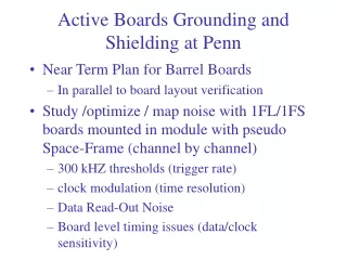
Active Boards Grounding and Shielding at Penn • Near Term Plan for Barrel Boards • In parallel to board layout verification • Study /optimize / map noise with 1FL/1FS boards mounted in module with pseudo Space-Frame (channel by channel) • 300 kHZ thresholds (trigger rate) • clock modulation (time resolution) • Data Read-Out Noise • Board level timing issues (data/clock sensitivity)
Pseudo-Barrel Module: PVC cylinder with Al foil. No attachment to module. Al Space Frame in both sides (not shown in photo)
300 kHz threshold for 10 DTMROC on 1FL on Module. Copper tape attached to Space Frame. Position 5 (chip Ad: 0x15) under investigation
1FL attached to the module. Clock Noise Modulation (50% point in each 3.2 ns bin)
1FL attached to the module. For each channel, difference in DAC counts between the 300 kHz threshold in any event, and in events acquired in coincidence with the DTMROC data read-out
1FL. Efficiency (all chips on the board) setting-reading back the ASD thresholds as a function of the Bunch crossing clock and data delay. Black color 100% efficiency
Optimize Grounding and Shielding configurations • Base line: outer (30 cm diameter shielded cylinder) attached to the space frame with no explicit connection to individual modules • Study effects of ground shield • 1FS/1FL before Peniscola • 1BL/BS after Peniscola (1-2 weeks) • Cooling Tests • Walter Konenko and students working on it • Next Slide: First look at 1FL on module
Board Level Tests • General Design • Confirm DTMROC DATA output amplitude uniformity • Measure test pulse level uniformity • Each Board Type • Investigate DATA/clock phase sensitivity • Study/investigate Clock/CMDIN amplitude requirements • Pulser based cross-talk studies • Including validation of the Protection InputBoard
Board Level Implementation • Stuffing / Debugging • Verify / Establish uniform component values and manufacturing specifications for stuffing diagrams and schematics • Cable maps on WWW for each board type • Electronic channel mapping on WWW
Multiple Tests at CERN • Merge Grounding and Shielding results from Penn • Configuration/verification for Module 1 • Add Module 2