Active Filter Design Techniques - 2
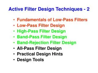
Active Filter Design Techniques - 2. Fundamentals of Low-Pass Filters Low-Pass Filter Design High-Pass Filter Design Band-Pass Filter Design Band-Rejection Filter Design All-Pass Filter Design Practical Design Hints Design Tools. Passive Filter. Active Filter.

Active Filter Design Techniques - 2
E N D
Presentation Transcript
Active Filter Design Techniques - 2 • Fundamentals of Low-Pass Filters • Low-Pass Filter Design • High-Pass Filter Design • Band-Pass Filter Design • Band-Rejection Filter Design • All-Pass Filter Design • Practical Design Hints • Design Tools
Passive Filter Active Filter Fundamentals of Low-Pass Filters A filter is a device that passes electric signals at certain frequencies or frequency ranges while preventing the passage of others. — Webster.
Passive Filter Active Filter Equivalent Filters Typical for filters > 1MHz. For freq < 1MHz, L is physically large.
Low-Pass Filter Design Transfer Function: Normalized Frequency:
Passive RC Low-Pass Filter Responses Gain Phase Roll-off Slope for 1st Order: 20dB/decade <= > 6dB/octave Phase Shift for 1st Order: 0º @ low freq -90º @ high freq
Non Ideal Filter Response Characteristics Uneven gain in the pass band Gradual transition from Passband to Stopband Gain Phase Nonlinear phase slope leading to distortion 1.5 Octaves Passband Stopband
Butterworth Filter Response Optimized for maximum flatness in the passband
Tschebyscheff Filter Optimized to sharpen the transition from passband to stopband Ripple in the Passband Steep Transition Slopes PassbandStopband
Filters Optimized to Sharpen the Transition from Passband to Stopband Ripple in Passband Ripple in Stopband
Ripple in Stopband Elliptic (Cauer) Filter Optimized for steepest transition from passband to stopband for a given filter order. Has ripple in both passband and stopband, however. Ripple in Passband
Infinite Impulse Response (IIR) Filter Design Template – Filter in Software
Bessel Filter Optimized for linear phase response up to fc
Group Delay • Group delay is a measure of the transit time of a signal versus frequency. • Group delay is a useful measure of phase distortion, and is calculated by differentiating the phase response versus frequency. Gain and Group Delay of a Bessel Filter Constant Group Delay and Linear Phase in Transition Region
Group Delay • Another way to say this is that group delay is a measure of the slope of the transmission phase response. • The linear portion of the phase response is converted to a constant value (representing the average signal-transit time) and deviations from linear phase are transformed into deviations from constant group delay. • The variations in group delay cause signal distortion, just as deviations from linear phase cause distortion.
Gain Response Phase Response Group delay Gain, Phase and Group Delays across Filter Types
Second Order Filter Implementation Sallen and Key Topology for 2nd Order Lowpass Filter Sallen and Key Topology for 2nd Order Lowpass Filter (Unity Gain)
Second Order Filter Implementation Sallen and Key Topology for 2nd Order Lowpass Filter Unity Gain
Sallen and Key Topology for 2nd Order Lowpass Filter Unity Gain
Second Order Filter Implementation Multiple FeedbackTopology for 2nd Order Lowpass Filter
Second Order Filter Implementation Multiple FeedbackTopology for 2nd Order Lowpass Filter Sallen and Key
Second Order Filter Implementation Multiple FeedbackTopology for 2nd Order Lowpass Filter
Second Order Filter Implementation Multiple FeedbackTopology for 2nd Order Lowpass Filter where
First Order High- and Low-pass Filter Topologies High-pass Low-pass Non inverting Inverting
First Order High- and Low-pass Filter Topologies Low-pass High-pass Non inverting Low-pass High-pass Exchange Rs with Cs Ω 1/Ω S 1/S
First Order High- and Low-pass Filter Topologies Non inverting Low-pass High-pass
First Order High- and Low-pass Filter Topologies High-pass Non inverting
Second Order High- and Low-pass Filter Topologies High-pass Low-pass Sallen and Key Multiple Feedback
S Low-pass to Band-pass Filter Design
S Low-pass to Band-pass Filter Design