LM-715 Supportability Analyses
LM-715 Supportability Analyses. Given a scenario, choose the appropriate supportability analyses tools and techniques. Illustrate the need for supportability analyses and their role as integral part of the systems engineering process.

LM-715 Supportability Analyses
E N D
Presentation Transcript
LM-715Supportability Analyses Given a scenario, choose the appropriate supportability analyses tools and techniques. • Illustrate the need for supportability analyses and their role as integral part of the systems engineering process. • Discuss supportability analyses methods throughout the system life cycle. • Identify the applicable tools and techniques of supportability analyses in the systems engineering process. • Relate the appropriate supportability analyses tools and techniques.
Supportability Analyses Logistics Anything analytical that has something to do with support Supportability Analyses LMI ? • SUPPORTABILITY ANALYSES: • Tailored application of engineering efforts during acquisition, to identify/solve logistics issues through an iterative SE process of definition, synthesis, tradeoff, T&E. (Mil Handbook 502) • LOGISTICS MANAGEMENT INFORMATION (LMI): • Documentation associated with supportability analyses. • [See MIL-PRF-49506]
Policy“Supportability factors are integral elements of program performance specification. However, support requirements are not to be stated as distinct logistic elements, but instead as performance requirements that relate to a system’s operational effectiveness, operational suitability, and life-cycle cost reduction.” DoD 5000.2-R
Policy • Supportability analyses are integral parts of Systems Engineering. • Supportability analyses form the basis for related design requirements in system specifications. • .Supportability analyses form the basis for decisions: how to most cost-effectively support a system over its life cycle. • Programs shall allow contractors maximum flexibility to propose most appropriate supportability analyses. DoD 5000.2-R
Integrated Supportability Analyses Can Include: • Maintenance Planning • Manpower, Personnel and Training • Facilities • Failure Modes, Effects and Criticality Analysis (FMECA) • PHS&T • Supply Support • Repair Level Analysis • Life Cycle Cost (LCC) Analysis. • Support & Test Equipment • etc. ....
Supportability Analyses Process Work Breakdown Structure Candidate Reliability Prediction FMECA RCM Common Source Engineering Data Base LORA Maint. Planning Spares Training PHS&T Personnel Technical Data Tools & Support Equip Facilities Computer Resources Support O & S COST
BEST PRACTICE: Supportability Analyses • Tailored ! • Part of iterative SE process • Assists in: • Defining support • Influencing design • Uses (not duplicates) other data & analyses • Documented and communicated
Supportability Analyses in Practice Maintenance Concept A Maintenance Concept B Maintenance Concept C Logistics IPT Supportability Analyses Results Specification Support Plan
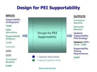
Supportability Is a Design Requirement - Not the Result of the Design • Early focus results in: • support parameters stated in operational terms • readiness objectives • support costs • Achieving & sustaining affordable system supportability [AKA - Affordable Readiness] is the result of sound systems engineering
Supportability Analyses Provide Input to the Systems Engineering Strategy • Strategy should address all supportability analyses needed to: • analyze, define and verify supportability threshold & objectives • assess the risk in meeting the thresholds & objectives
Supportability Analysis Provides Input into the TEMP • Methods & techniques encompass: • technical reviews • modeling & simulation • demonstration • testing • All support performance requirements should be tested & verified.
Supportability Analyses for Commercial and NDI? • Questions: • Commercial and NDI have sufficient data? • Commercial and NDI used in the same “operational” environment? • Commercial and NDI supportable with the same maintenance/logistic concept? • Results impact choice of supportability analyses
Maintenance Planning Summaries Supportability Analyses ReportsExamples Phases Concept Exploration Program Def. and Risk Red. Engineering & Manuf. Dev. Prod., Fielding/ Deployment, Operational Spt. Preconcept Repair Analysis Summaries Manpower, Personnel and Training Summaries Supply Support Summaries Support & Test Equipment Summaries Facilities Summaries PHS&T Summaries Post Production Support Summaries These “and other*” reports to be tailored to Program needs. *not all inclusive nor exclusive Source: Mil-Hdbk-502
Scientific Method Process Observation Problem Formulation State Research objectives Determine Casual Relationship Formulate Hypothesis State Research Methodology Test Hypothesis Formulate conclusions Communicate findings Nine Phase Decision Process Monitor Environment Define Problem Specify objective Diagnose the Problem Develop alternatives Establish Evaluation Criteria Appraise alternatives Choose Best Alternative[s] Implement Decision HOW DO YOU DO SUPPORTABILITY ANALYSES? When all else fails, use your Common Sense!
SYSTEM NAME SPACE SHUTTLE MP SRM 10-00 SUBSYSTEM NAME SRM CASE 10-06 COMPONENT NAME AND PART NO. CASE ASSEMBLY, FORWARD 10-05-01 SEGMENT 1U50147-08 COMPONENT FUNCTION AUTHOR AND COMPANY W. L. HANKINE THIOKOL CORPORATION DATE JUNE 1983 REVISION FAILURE EFFECT ON A. SUBSYSTEM FUNCTION B. SYSTEM FUNCTION C. MISSION D. VEHICLE AND PERSONNEL MISSION PHASE COMPONENT FAILURE MODE AFFECTED COMPONENT CONTROL METHODS TO INSURE A RELIABLE PRODUCT CRITICALITY CATEGORY A. HIGH TEMPERATURE GAS FLOW WILL CAUSE METAL EROSION AND PROBABLE BURNTHROUGH AND CASE BURST. B. CATASTROPHIC FAILURE OF SRM. C. MISSION LOSS. D.VEHICLE AND PERSONNEL LOSS. 1 (1) (1R) (1R) (1R) (1) (1R) (1R) (1R) (1R) SEE CIL 1. TRAINED, QUALIFIED MACHINIST TO PERFORM MACHINING OPERATION. 2. SPECIAL PROFILE TEMPLATE TO CONTROL LATHE CUTTING HEAD. 3. 100% INSPECTION OF TANG- DIAMETER, CLEVIS, DIMEN - SIONS AND O-RING GROOVES USING PI TAPE AND STAND- DARD MEASURING INSTRU- MENTS . SURFACE FINISH SAMPLE INSPECTED BY SURF-INDICATOR. 7. A. TRAINED, QUALIFIED MACHINIST TO PERFORM MACHINING OPERATION. B. 100% INSPECTION OF IGNITER FLANGE FLATNESS BY TIR READOUT FINISH IS SAMPLE INSPECTED USING SURF-INDICATOR. ASSEMBLY JOINTS LEAK. QUANTITY PER COMPONENT PART NO. PART NAME CASE SEGMENT, CYLINDER CASE SEGMENT, FORWARD PACKING (O-RINGS) TEST PLUG PACKING (TEST PLUG) 1U50131-09 1U51473-01 1U50228-24 1U100269-01 1U50228-15 2 1 2/JOINT 1/JOINT 1/PLUG 1. TANG-A-DIAMETER EXCEEDS UPPER LIMIT OR SURFACE FINISH NONCONFORMING, OR IS GOUGEDRFACES. 2. CLEVIS NONCONFORMING (DIAMETER, THICKNESS, FINISH). 3. CLEVIS O-RING GROOVES EXCEED WIDTH AND/OR DEPTH UPPER LIMITS OR CORRODED. 4. 0-RINGS NONCONFORMING OR DAMAGED DURING ASSEM- BLY. 5. LEAK CHECK PLUG LOOSE OR WITHOUT O-RING, INNERMOST SEAL INEFFECTIVE PER 1 ABOVE OR THE CONDITIONS OF O- RING ARE PER 4 ABOVE. 6. FOREIGN MATERIAL IN O-RING GROOVES. 7. IGNITER FLANGE NONCONFORMING, FLATNESS FINISH. 8. CASE ASSEMBLY JOINT ROTATION CAUSES “LIFT-OFF” FROM SECONDARY O-RING (PRIMARY O-RING WILL REMAIN IN COMPRESSION). 9. EXPANSION OF CLEVIS GAP BECAUSE OF RESIDUAL STRAINS RESULTING FROM MANUFACTURING PROCESSES. Number PAGE OF FAILURE MODES, EFFECTS AND CRITICALITY ANALYSIS (FMECA) Example