Download
1 / 58
580 likes | 602 Views
This reading material discusses the principles and practice of parameterized design in VHDL, specifically for modeling circuits with a regular structure. It includes examples and schemes for equation generation and component instantiation.

E N D
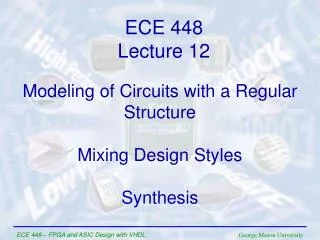
ECE 545 Lecture 10 Parameterized Design:Modeling of Circuits with a RegularStructure
Required reading • P. Chu, RTL Hardware Design using VHDL • Chapter 14, Parameterized Design: Principle • Chapter 15, Parameterized Design: Practice
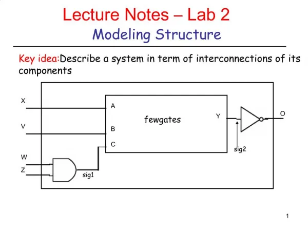
Generate scheme for equations ECE 448 – FPGA and ASIC Design with VHDL
Data-flow VHDL Major instructions Concurrent statements • concurrent signal assignment () • conditional concurrent signal assignment • (when-else) • selected concurrent signal assignment • (with-select-when) • generate scheme for equations • (for-generate)
PARITY: Entity Declaration LIBRARYieee; USEieee.std_logic_1164.all; ENTITYparityIS PORT( parity_in : IN STD_LOGIC_VECTOR(7 DOWNTO 0); parity_out : OUT STD_LOGIC ); ENDparity;
PARITY: Block Diagram xor_out(1) xor_out(2) xor_out(3) xor_out(4) xor_out(5) xor_out(6)
PARITY: Architecture ARCHITECTUREparity_dataflowOFparityIS SIGNALxor_out: std_logic_vector (6 downto 1); BEGIN xor_out(1) <= parity_in(0) XORparity_in(1); xor_out(2) <= xor_out(1) XORparity_in(2); xor_out(3) <= xor_out(2) XORparity_in(3); xor_out(4) <= xor_out(3) XORparity_in(4); xor_out(5) <= xor_out(4) XORparity_in(5); xor_out(6) <= xor_out(5) XORparity_in(6); parity_out <= xor_out(6) XORparity_in(7); ENDparity_dataflow;
PARITY: Block Diagram (2) xor_out(1) xor_out(0) xor_out(2) xor_out(3) xor_out(4) xor_out(5) xor_out(6) xor_out(7)
PARITY: Architecture ARCHITECTUREparity_dataflowOFparityIS SIGNALxor_out: STD_LOGIC_VECTOR (7 downto 0); BEGIN xor_out(0) <= parity_in(0); xor_out(1) <= xor_out(0) XORparity_in(1); xor_out(2) <= xor_out(1) XORparity_in(2); xor_out(3) <= xor_out(2) XORparity_in(3); xor_out(4) <= xor_out(3) XORparity_in(4); xor_out(5) <= xor_out(4) XORparity_in(5); xor_out(6) <= xor_out(5) XORparity_in(6); xor_out(7) <= xor_out(6) XORparity_in(7); parity_out <= xor_out(7); ENDparity_dataflow;
PARITY: Architecture (2) ARCHITECTUREparity_dataflowOFparityIS SIGNALxor_out: STD_LOGIC_VECTOR (7 DOWNTO 0); BEGIN xor_out(0) <= parity_in(0); G2: FOR i IN1TO7GENERATE xor_out(i) <= xor_out(i-1) XORparity_in(i); END GENERATE G2; parity_out <= xor_out(7); ENDparity_dataflow;
For Generate Statement For - Generate label:FORidentifier IN rangeGENERATE BEGIN {Concurrent Statements} END GENERATE;
Generate scheme for components ECE 448 – FPGA and ASIC Design with VHDL
Structural VHDL Major instructions • component instantiation (port map) • component instantiation with generic • (generic map, port map) • generate scheme for component instantiations • (for-generate)
Example 1 s 0 s 1 w 0 w 3 s w 2 4 s 3 w 7 f w 8 w 11 w 12 w 15
A 4-to-1 Multiplexer LIBRARY ieee ; USE ieee.std_logic_1164.all ; ENTITY mux4to1 IS PORT ( w0, w1, w2, w3 : IN STD_LOGIC ; s : IN STD_LOGIC_VECTOR(1 DOWNTO 0) ; f : OUT STD_LOGIC ) ; END mux4to1 ; ARCHITECTURE Dataflow OF mux4to1 IS BEGIN WITH s SELECT f <= w0 WHEN "00", w1 WHEN "01", w2 WHEN "10", w3 WHEN OTHERS ; END Dataflow ;
Straightforward code for Example 1 LIBRARY ieee ; USE ieee.std_logic_1164.all ; ENTITY Example1 IS PORT ( w : IN STD_LOGIC_VECTOR(0 TO 15) ; s : IN STD_LOGIC_VECTOR(3 DOWNTO 0) ; f : OUT STD_LOGIC ) ; END Example1 ;
Straightforward code for Example 1 ARCHITECTURE Structure OF Example1 IS COMPONENT mux4to1 PORT ( w0, w1, w2, w3 : IN STD_LOGIC ; s : IN STD_LOGIC_VECTOR(1 DOWNTO 0) ; f : OUT STD_LOGIC ) ; END COMPONENT ; SIGNAL m : STD_LOGIC_VECTOR(0 TO 3) ; BEGIN Mux1: mux4to1 PORT MAP ( w(0), w(1), w(2), w(3), s(1 DOWNTO 0), m(0) ) ; Mux2: mux4to1 PORT MAP ( w(4), w(5), w(6), w(7), s(1 DOWNTO 0), m(1) ) ; Mux3: mux4to1 PORT MAP ( w(8), w(9), w(10), w(11), s(1 DOWNTO 0), m(2) ) ; Mux4: mux4to1 PORT MAP ( w(12), w(13), w(14), w(15), s(1 DOWNTO 0), m(3) ) ; Mux5: mux4to1 PORT MAP ( m(0), m(1), m(2), m(3), s(3 DOWNTO 2), f ) ; END Structure ;
Modified code for Example 1 ARCHITECTURE Structure OF Example1 IS COMPONENT mux4to1 PORT ( w0, w1, w2, w3 : IN STD_LOGIC ; s : IN STD_LOGIC_VECTOR(1 DOWNTO 0) ; f : OUT STD_LOGIC ) ; END COMPONENT ; SIGNAL m : STD_LOGIC_VECTOR(0 TO 3) ; BEGIN G1: FOR i IN 0 TO 3 GENERATE Muxes: mux4to1 PORT MAP ( w(4*i), w(4*i+1), w(4*i+2), w(4*i+3), s(1 DOWNTO 0), m(i) ) ; END GENERATE ; Mux5: mux4to1 PORT MAP ( m(0), m(1), m(2), m(3), s(3 DOWNTO 2), f ) ; END Structure ;
Example 2 w y w y 1 15 1 3 w y w y 0 14 0 2 y y 13 1 y y En 12 0 y w y 11 1 3 w y y 0 2 10 y y 1 9 w w y y y 3 En 1 3 0 8 w w y 2 0 2 y 1 y w w y y En En 7 1 3 0 y w y 6 0 2 y y 1 5 y y En 0 4 y w y 3 1 3 y w y 2 0 2 y y 1 1 y y En 0 0
A 2-to-4 binary decoder LIBRARY ieee ; USE ieee.std_logic_1164.all ; ENTITY dec2to4 IS PORT ( w : IN STD_LOGIC_VECTOR(1 DOWNTO 0) ; En : IN STD_LOGIC ; y : OUT STD_LOGIC_VECTOR(3 DOWNTO 0) ) ; END dec2to4 ; ARCHITECTURE Dataflow OF dec2to4 IS SIGNAL Enw : STD_LOGIC_VECTOR(2 DOWNTO 0) ; BEGIN Enw <= En & w ; WITH Enw SELECT y <= "0001" WHEN "100", "0010" WHEN "101", "0100" WHEN "110", “1000" WHEN "111", "0000" WHEN OTHERS ; END Dataflow ;
VHDL code for Example 2 (1) LIBRARY ieee ; USE ieee.std_logic_1164.all ; ENTITY dec4to16 IS PORT (w : IN STD_LOGIC_VECTOR(3 DOWNTO 0) ; En : IN STD_LOGIC ; y : OUT STD_LOGIC_VECTOR(15 DOWNTO 0) ) ; END dec4to16 ;
VHDL code for Example 2 (2) ARCHITECTURE Structure OF dec4to16 IS COMPONENT dec2to4 PORT ( w : IN STD_LOGIC_VECTOR(1 DOWNTO 0) ; En : IN STD_LOGIC ; y : OUT STD_LOGIC_VECTOR(3 DOWNTO 0) ) ; END COMPONENT ; SIGNAL m : STD_LOGIC_VECTOR(3 DOWNTO 0) ; BEGIN G1: FOR i IN 0 TO 3 GENERATE Dec_ri: dec2to4 PORT MAP ( w(1 DOWNTO 0), m(i), y(4*i+3 DOWNTO 4*i) ); END GENERATE ; Dec_left: dec2to4 PORT MAP ( w(3 DOWNTO 2), En, m ) ; END Structure ;
Example 3 Variable Rotator
Example 3: Variable rotator - Interface A 16 4 B A <<< B 16 C
VHDL code for a 16-bit 2-to-1 Multiplexer LIBRARY ieee ; USE ieee.std_logic_1164.all ; ENTITY mux2to1_16 IS PORT ( w0 : IN STD_LOGIC_VECTOR(15 DOWNTO 0); w1 : IN STD_LOGIC_VECTOR(15 DOWNTO 0); s : IN STD_LOGIC ; f : OUT STD_LOGIC_VECTOR(15 DOWNTO 0) ) ; END mux2to1_16 ; ARCHITECTURE dataflow OF mux2to1_16 IS BEGIN f <= w0 WHEN s = '0' ELSE w1 ; END dataflow ;
Fixed rotation a(15) a(14) a(13) a(12) a(11) a(10) a(9) a(8) a(7) a(6) a(5) a(4) a(3) a(2) a(1) a(0) a(12) a(11) a(10) a(9) a(8) a(7) a(6) a(5) a(4) a(3) a(2) a(1) a(0) a(15) a(14) a(13) <<< 3 y <= a(12 downto 0) & a(15 downto 13); a(15) a(14) a(13) a(12) a(11) a(10) a(9) a(8) a(7) a(6) a(5) a(4) a(3) a(2) a(1) a(0) a(10) a(9) a(8) a(7) a(6) a(5) a(4) a(3) a(2) a(1) a(0) a(15) a(14) a(13) a(12) a(11) <<< 5 y <= a(10 downto 0) & a(15 downto 11);
Fixed rotation by L positions a(15) a(14) a(13) a(12) a(11) a(10) a(9) a(8) a(7) a(6) a(5) a(4) a(3) a(2) a(1) a(0) a(15-L) a(15-L-1) . . . . . . . . . . . . . . a(1) a(0) a(15) a(14) . . . . . . . a(15-L+2) a(15-L+1) <<< L y <= a(15-L downto 0) & a(15 downto 15-L+1);
VHDL code forfor a fixed 16-bit rotator LIBRARY ieee ; USE ieee.std_logic_1164.all ; ENTITY fixed_rotator_left_16 IS GENERIC ( L : INTEGER := 1); PORT ( a : IN STD_LOGIC_VECTOR(15 DOWNTO 0); y : OUT STD_LOGIC_VECTOR(15 DOWNTO 0) ) ; END fixed_rotator_left_16 ; ARCHITECTURE dataflow OF fixed_rotator_left_16 IS BEGIN y <= a(15-L downto 0) & a(15 downto 15-L+1); END dataflow ;
Structural VHDL code forfor a variable 16-bit rotator (1) LIBRARY ieee ; USE ieee.std_logic_1164.all ; ENTITY variable_rotator_16 is PORT( A : IN STD_LOGIC_VECTOR(15 downto 0); B : IN STD_LOGIC_VECTOR(3 downto 0); C : OUT STD_LOGIC_VECTOR(15 downto 0) ); END variable_rotator_16;
Structural VHDL code forfor a variable 16-bit rotator (2) LIBRARY ieee ; USE ieee.std_logic_1164.all ; ARCHITECTURE structural OF variable_rotator_16 IS COMPONENT mux2to1_16 PORT ( w0 : IN STD_LOGIC_VECTOR(15 DOWNTO 0); w1 : IN STD_LOGIC_VECTOR(15 DOWNTO 0); s : IN STD_LOGIC ; f : OUT STD_LOGIC_VECTOR(15 DOWNTO 0) ) ; END COMPONENT ; COMPONENT fixed_rotator_left_16 GENERIC ( L : INTEGER := 1); PORT ( a : IN STD_LOGIC_VECTOR(15 DOWNTO 0); y : OUT STD_LOGIC_VECTOR(15 DOWNTO 0) ) ; END COMPONENT ;
Structural VHDL code forfor a variable 16-bit rotator (3) TYPE array1 IS ARRAY (0 to 4) OF STD_LOGIC_VECTOR(15 DOWNTO 0); TYPE array2 IS ARRAY (0 to 3) OF STD_LOGIC_VECTORS(15 DOWNTO 0); SIGNAL Al : array1; SIGNAL Ar : array2; BEGIN Al(0) <= A; G: FOR i IN 0 TO 3 GENERATE ROT_I: fixed_rotator_left_16 GENERIC MAP (L => 2** i) PORT MAP ( a => Al(i) , y => Ar(i)); MUX_I: mux2to1_16 PORT MAP (w0 => Al(i), w1 => Ar(i), s => B(i), f => Al(i+1)); END GENERATE; C <= Al(4); END variable_rotator_16;
Aliases ECE 448 – FPGA and ASIC Design with VHDL
Aliases Syntax: ALIAS name : type := expression; Example: signal IR : std_logic_vector(31 downto 0); alias IR_opcode : std_logic_vector(5 downto 0) is IR(31 downto 26); alias IR_reg1_addr : std_logic_vector(4 downto 0) is IR(25 downto 21); alias IR_reg2_addr : std_logic_vector(4 downto 0) is IR(20 downto 16);
Constants ECE 448 – FPGA and ASIC Design with VHDL
Constants Syntax: CONSTANT name : type := value; Examples: CONSTANT init_value : STD_LOGIC_VECTOR(3 downto 0) := "0100"; CONSTANT ANDA_EXT : STD_LOGIC_VECTOR(7 downto 0) := X"B4"; CONSTANT counter_width : INTEGER := 16; CONSTANT buffer_address : INTEGER := 16#FFFE#; CONSTANT clk_period : TIME := 20 ns; CONSTANT strobe_period : TIME := 333.333 ms;
Constants - features Constantscan be declared in a PACKAGE, ENTITY, ARCHITECTURE When declared in a PACKAGE, the constant is truly global, for the package can be used in several entities. When declared in an ARCHITECTURE, the constant is local, i.e., it is visible only within this architecture. When declared in an ENTITY declaration, the constant can be used in all architectures associated with this entity.
Packages ECE 448 – FPGA and ASIC Design with VHDL
Explicit Component Declaration versus Package • Explicit component declaration is when you declare components in main code • When have only a few component declarations, this is fine • When have many component declarations, use packages for readability • Packages also help with portability and sharing of libraries among many users in a company • Remember, the actual instantiations always take place in main code • Only the declarations can be in main code or package
Explicit Component Declaration Tips • For simple projects put entity .vhd files all in same directory • Declare components in main code • If using Aldec, make sure compiler knows the correct hierarchy • From lowest to highest • Xilinx will figure out hierarchy automatically
METHOD #2: Package component declaration • Components declared in package • Actual instantiations and port maps always in main code
Packages • Instead of declaring all components can declare all components in a PACKAGE, and INCLUDE the package once • This makes the top-level entity code cleaner • It also allows that complete package to be used by another designer • A package can contain • Components • Functions, Procedures • Types, Constants
Package – example (1) LIBRARY ieee ; USE ieee.std_logic_1164.all ; PACKAGE GatesPkg IS COMPONENT mux2to1 PORT (w0, w1, s : IN STD_LOGIC ; f : OUT STD_LOGIC ) ; END COMPONENT ; COMPONENT priority PORT (w : IN STD_LOGIC_VECTOR(3 DOWNTO 0) ; y : OUT STD_LOGIC_VECTOR(1 DOWNTO 0) ; z : OUT STD_LOGIC ) ; END COMPONENT ;
Package – example (2) COMPONENT dec2to4 PORT (w : IN STD_LOGIC_VECTOR(1 DOWNTO 0) ; En : IN STD_LOGIC ; y : OUT STD_LOGIC_VECTOR(0 TO 3) ) ; END COMPONENT ; COMPONENT regn GENERIC ( N : INTEGER := 8 ) ; PORT ( D : IN STD_LOGIC_VECTOR(N-1 DOWNTO 0) ; Enable, Clock : IN STD_LOGIC ; Q : OUT STD_LOGIC_VECTOR(N-1 DOWNTO 0) ) ; END COMPONENT ;
Package – example (3) • constant ADDAB : std_logic_vector(3 downto 0) := "0000"; • constant ADDAM : std_logic_vector(3 downto 0) := "0001"; • constant SUBAB : std_logic_vector(3 downto 0) := "0010"; • constant SUBAM : std_logic_vector(3 downto 0) := "0011"; • constant NOTA : std_logic_vector(3 downto 0) := "0100"; • constant NOTB : std_logic_vector(3 downto 0) := "0101"; • constant NOTM : std_logic_vector(3 downto 0) := "0110"; • constant ANDAB : std_logic_vector(3 downto 0) := "0111"; • END GatesPkg;