Download
1 / 93
930 likes | 946 Views
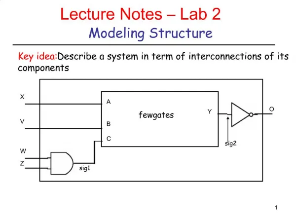
Learn how to model and implement parity circuits using VHDL, covering dataflow and structural design styles, with detailed examples and code snippets.

E N D
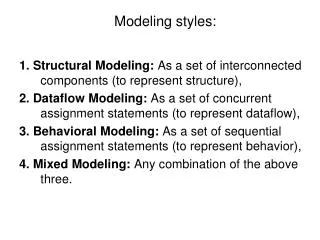
ECE 545 Lecture 7 Modeling of Circuits with a RegularStructureAliases, Attributes, PackagesMixing Design Styles
Required reading • P. Chu, RTL Hardware Design using VHDL • Chapters • 14.5 For Generate Statement • 14.6 Conditional Generate Statement • 15.2 Data Types for Two-Dimensional Signals • 15.3 Commonly Used Intermediate-Sized • RT-Level Components
Generate scheme for equations ECE 448 – FPGA and ASIC Design with VHDL
Dataflow VHDL Major instructions Concurrent statements • concurrent signal assignment () • conditional concurrent signal assignment • (when-else) • selected concurrent signal assignment • (with-select-when) • generate scheme for equations • (for-generate)
PARITY: Entity Declaration LIBRARYieee; USEieee.std_logic_1164.all; ENTITYparityIS PORT( parity_in : IN STD_LOGIC_VECTOR(7 DOWNTO 0); parity_out : OUT STD_LOGIC ); ENDparity;
PARITY: Block Diagram xor_out(1) xor_out(2) xor_out(3) xor_out(4) xor_out(5) xor_out(6)
PARITY: Architecture ARCHITECTUREparity_dataflowOFparityIS SIGNALxor_out: std_logic_vector (6 downto 1); BEGIN xor_out(1) <= parity_in(0) XORparity_in(1); xor_out(2) <= xor_out(1) XORparity_in(2); xor_out(3) <= xor_out(2) XORparity_in(3); xor_out(4) <= xor_out(3) XORparity_in(4); xor_out(5) <= xor_out(4) XORparity_in(5); xor_out(6) <= xor_out(5) XORparity_in(6); parity_out <= xor_out(6) XORparity_in(7); ENDparity_dataflow;
PARITY: Architecture (2) ARCHITECTUREparity_dataflowOFparityIS SIGNALxor_out: STD_LOGIC_VECTOR (6 DOWNTO 1); BEGIN G2: FOR i IN1TO7GENERATE left_xor: IF i=1 GENERATE xor_out(i) <= parity_in(i-1) XORparity_in(i); END GENERATE; middle_xor: IF (i >1) AND (i<7) GENERATE xor_out(i) <= xor_out(i-1) XORparity_in(i); END GENERATE; right_xor: IF i=7 GENERATE parity_out <= xor_out(i-1) XORparity_in(i); END GENERATE; END GENERATE; ENDparity_dataflow;
PARITY: Block Diagram (2) xor_out(1) xor_out(0) xor_out(2) xor_out(3) xor_out(4) xor_out(5) xor_out(6) xor_out(7)
PARITY: Architecture ARCHITECTUREparity_dataflowOFparityIS SIGNALxor_out: STD_LOGIC_VECTOR (7 downto 0); BEGIN xor_out(0) <= parity_in(0); xor_out(1) <= xor_out(0) XORparity_in(1); xor_out(2) <= xor_out(1) XORparity_in(2); xor_out(3) <= xor_out(2) XORparity_in(3); xor_out(4) <= xor_out(3) XORparity_in(4); xor_out(5) <= xor_out(4) XORparity_in(5); xor_out(6) <= xor_out(5) XORparity_in(6); xor_out(7) <= xor_out(6) XORparity_in(7); parity_out <= xor_out(7); ENDparity_dataflow;
PARITY: Architecture (2) ARCHITECTUREparity_dataflowOFparityIS SIGNALxor_out: STD_LOGIC_VECTOR (7DOWNTO 0); BEGIN xor_out(0) <= parity_in(0); G2: FOR i IN1TO7GENERATE xor_out(i) <= xor_out(i-1) XORparity_in(i); END GENERATE G2; parity_out <= xor_out(7); ENDparity_dataflow;
For Generate Statement For - Generate label: FORidentifier IN rangeGENERATE {Concurrent Statements} END GENERATE;
Conditional Generate Statement If -Generate label: IFboolean_expressionGENERATE {Concurrent Statements} END GENERATE;
Generate scheme for components ECE 448 – FPGA and ASIC Design with VHDL
Structural VHDL Major instructions • component instantiation (port map) • component instantiation with generic • (generic map, port map) • generate scheme for component instantiations • (for-generate)
Example 1 s 0 s 1 w 0 w 3 s w 2 4 s 3 w 7 f w 8 w 11 w 12 w 15
A 4-to-1 Multiplexer LIBRARY ieee ; USE ieee.std_logic_1164.all ; ENTITY mux4to1 IS PORT ( w0, w1, w2, w3 : IN STD_LOGIC ; s : IN STD_LOGIC_VECTOR(1 DOWNTO 0) ; f : OUT STD_LOGIC ) ; END mux4to1 ; ARCHITECTURE Dataflow OF mux4to1 IS BEGIN WITH s SELECT f <= w0 WHEN "00", w1 WHEN "01", w2 WHEN "10", w3 WHEN OTHERS ; END Dataflow ;
Straightforward code for Example 1 LIBRARY ieee ; USE ieee.std_logic_1164.all ; ENTITY Example1 IS PORT ( w : IN STD_LOGIC_VECTOR(0 TO 15) ; s : IN STD_LOGIC_VECTOR(3 DOWNTO 0) ; f : OUT STD_LOGIC ) ; END Example1 ;
Straightforward code for Example 1 ARCHITECTURE Structure OF Example1 IS COMPONENT mux4to1 PORT ( w0, w1, w2, w3 : IN STD_LOGIC ; s : IN STD_LOGIC_VECTOR(1 DOWNTO 0) ; f : OUT STD_LOGIC ) ; END COMPONENT ; SIGNAL m : STD_LOGIC_VECTOR(0 TO 3) ; BEGIN Mux1: mux4to1 PORT MAP ( w(0), w(1), w(2), w(3), s(1 DOWNTO 0), m(0) ) ; Mux2: mux4to1 PORT MAP ( w(4), w(5), w(6), w(7), s(1 DOWNTO 0), m(1) ) ; Mux3: mux4to1 PORT MAP ( w(8), w(9), w(10), w(11), s(1 DOWNTO 0), m(2) ) ; Mux4: mux4to1 PORT MAP ( w(12), w(13), w(14), w(15), s(1 DOWNTO 0), m(3) ) ; Mux5: mux4to1 PORT MAP ( m(0), m(1), m(2), m(3), s(3 DOWNTO 2), f ) ; END Structure ;
Modified code for Example 1 ARCHITECTURE Structure OF Example1 IS COMPONENT mux4to1 PORT ( w0, w1, w2, w3 : IN STD_LOGIC ; s : IN STD_LOGIC_VECTOR(1 DOWNTO 0) ; f : OUT STD_LOGIC ) ; END COMPONENT ; SIGNAL m : STD_LOGIC_VECTOR(0 TO 3) ; BEGIN G1: FOR i IN 0 TO 3 GENERATE Muxes: mux4to1 PORT MAP ( w(4*i), w(4*i+1), w(4*i+2), w(4*i+3), s(1 DOWNTO 0), m(i) ) ; END GENERATE ; Mux5: mux4to1 PORT MAP ( m(0), m(1), m(2), m(3), s(3 DOWNTO 2), f ) ; END Structure ;
Example 2 w y w y 1 15 1 3 w y w y 0 14 0 2 y y 13 1 y y En 12 0 y w y 11 1 3 w y y 0 2 10 y y 1 9 w w y y y 3 En 1 3 0 8 w w y 2 0 2 y 1 y w w y y En En 7 1 3 0 y w y 6 0 2 y y 1 5 y y En 0 4 y w y 3 1 3 y w y 2 0 2 y y 1 1 y y En 0 0
A 2-to-4 binary decoder LIBRARY ieee ; USE ieee.std_logic_1164.all ; ENTITY dec2to4 IS PORT ( w : IN STD_LOGIC_VECTOR(1 DOWNTO 0) ; En : IN STD_LOGIC ; y : OUT STD_LOGIC_VECTOR(3 DOWNTO 0) ) ; END dec2to4 ; ARCHITECTURE Dataflow OF dec2to4 IS SIGNAL Enw : STD_LOGIC_VECTOR(2 DOWNTO 0) ; BEGIN Enw <= En & w ; WITH Enw SELECT y <= "0001" WHEN "100", "0010" WHEN "101", "0100" WHEN "110", “1000" WHEN "111", "0000" WHEN OTHERS ; END Dataflow ;
VHDL code for Example 2 (1) LIBRARY ieee ; USE ieee.std_logic_1164.all ; ENTITY dec4to16 IS PORT (w : IN STD_LOGIC_VECTOR(3 DOWNTO 0) ; En : IN STD_LOGIC ; y : OUT STD_LOGIC_VECTOR(15 DOWNTO 0) ) ; END dec4to16 ;
VHDL code for Example 2 (2) ARCHITECTURE Structure OF dec4to16 IS COMPONENT dec2to4 PORT ( w : IN STD_LOGIC_VECTOR(1 DOWNTO 0) ; En : IN STD_LOGIC ; y : OUT STD_LOGIC_VECTOR(3 DOWNTO 0) ) ; END COMPONENT ; SIGNAL m : STD_LOGIC_VECTOR(3 DOWNTO 0) ; BEGIN G1: FOR i IN 0 TO 3 GENERATE Dec_ri: dec2to4 PORT MAP ( w(1 DOWNTO 0), m(i), y(4*i+3 DOWNTO 4*i) ); END GENERATE ; Dec_left: dec2to4 PORT MAP ( w(3 DOWNTO 2), En, m ) ; END Structure ;
Example 3 Up-or-down Free Running Counter
Up-or-down Free Running Counter (1) library ieee; use ieee.std_logic_1164.all; use ieee.numeric_std.all; entity up_or_down_counter is generic( WIDTH: natural:=4; UP: natural:=0 ); port( clk, reset: in std_logic; q: out std_logic_vector(WIDTH-1 downto 0) ); end up_or_down_counter;
Up-or-down Free Running Counter (2) architecture arch of up_or_down_counter is signal r_reg: unsigned(WIDTH-1 downto 0); signal r_next: unsigned(WIDTH-1 downto 0); begin -- register process(clk,reset) begin if (reset='1') then r_reg <= (others=>'0'); elsif (clk'event and clk='1') then r_reg <= r_next; end if; end process;
Up-or-down Free Running Counter (3) -- next-state logic inc_gen: -- incrementor if UP=1 generate r_next <= r_reg + 1; end generate; dec_gen: --decrementor if UP/=1 generate r_next <= r_reg – 1; end generate; -- output logic q <= std_logic_vector(r_reg); end arch;
Example 4 Up-and-down Free Running Counter
Up-and-down Free Running Counter (1) library ieee; use ieee.std_logic_1164.all; use ieee.numeric_std.all; entity up_and_down_counter is generic(WIDTH: natural:=4); port( clk, reset: in std_logic; mode: in std_logic; q: out std_logic_vector(WIDTH-1 downto 0) ); end up_and_down_counter;
Up-and-down Free Running Counter (2) architecture arch of up_and_down_counter is signal r_reg: unsigned(WIDTH-1 downto 0); signal r_next: unsigned(WIDTH-1 downto 0); begin -- register process(clk,reset) begin if (reset='1') then r_reg <= (others=>'0'); elsif (clk'event and clk='1') then r_reg <= r_next; end if; end process;
Up-and-down Free Running Counter (3) -- next-state logic r_next <= r_reg + 1 when mode='1' else r_reg - 1; -- output logic q <= std_logic_vector(r_reg); end arch;
Example 5 Variable Rotator
Example 3: Variable rotator - Interface A 16 4 B A <<< B 16 C
VHDL code for a 16-bit 2-to-1 Multiplexer LIBRARY ieee ; USE ieee.std_logic_1164.all ; ENTITY mux2to1_16 IS PORT ( w0 : IN STD_LOGIC_VECTOR(15 DOWNTO 0); w1 : IN STD_LOGIC_VECTOR(15 DOWNTO 0); s : IN STD_LOGIC ; f : OUT STD_LOGIC_VECTOR(15 DOWNTO 0) ) ; END mux2to1_16 ; ARCHITECTURE dataflow OF mux2to1_16 IS BEGIN f <= w0 WHEN s = '0' ELSE w1 ; END dataflow ;
Fixed rotation a(15) a(14) a(13) a(12) a(11) a(10) a(9) a(8) a(7) a(6) a(5) a(4) a(3) a(2) a(1) a(0) a(12) a(11) a(10) a(9) a(8) a(7) a(6) a(5) a(4) a(3) a(2) a(1) a(0) a(15) a(14) a(13) <<< 3 y <= a(12 downto 0) & a(15 downto 13); a(15) a(14) a(13) a(12) a(11) a(10) a(9) a(8) a(7) a(6) a(5) a(4) a(3) a(2) a(1) a(0) a(10) a(9) a(8) a(7) a(6) a(5) a(4) a(3) a(2) a(1) a(0) a(15) a(14) a(13) a(12) a(11) <<< 5 y <= a(10 downto 0) & a(15 downto 11);
Fixed rotation by L positions a(15) a(14) a(13) a(12) a(11) a(10) a(9) a(8) a(7) a(6) a(5) a(4) a(3) a(2) a(1) a(0) a(15-L) a(15-L-1) . . . . . . . . . . . . . . a(1) a(0) a(15) a(14) . . . . . . . a(15-L+2) a(15-L+1) <<< L y <= a(15-L downto 0) & a(15 downto 15-L+1);
VHDL code forfor a fixed 16-bit rotator LIBRARY ieee ; USE ieee.std_logic_1164.all ; ENTITY fixed_rotator_left_16 IS GENERIC ( L : INTEGER := 1); PORT ( a : IN STD_LOGIC_VECTOR(15 DOWNTO 0); y : OUT STD_LOGIC_VECTOR(15 DOWNTO 0) ) ; END fixed_rotator_left_16 ; ARCHITECTURE dataflow OF fixed_rotator_left_16 IS BEGIN y <= a(15-L downto 0) & a(15 downto 15-L+1); END dataflow ;
Structural VHDL code forfor a variable 16-bit rotator (1) LIBRARY ieee ; USE ieee.std_logic_1164.all ; ENTITY variable_rotator_16 is PORT( A : IN STD_LOGIC_VECTOR(15 downto 0); B : IN STD_LOGIC_VECTOR(3 downto 0); C : OUT STD_LOGIC_VECTOR(15 downto 0) ); END variable_rotator_16;
Structural VHDL code forfor a variable 16-bit rotator (2) LIBRARY ieee ; USE ieee.std_logic_1164.all ; ARCHITECTURE structural OF variable_rotator_16 IS COMPONENT mux2to1_16 PORT ( w0 : IN STD_LOGIC_VECTOR(15 DOWNTO 0); w1 : IN STD_LOGIC_VECTOR(15 DOWNTO 0); s : IN STD_LOGIC ; f : OUT STD_LOGIC_VECTOR(15 DOWNTO 0) ) ; END COMPONENT ; COMPONENT fixed_rotator_left_16 GENERIC ( L : INTEGER := 1); PORT ( a : IN STD_LOGIC_VECTOR(15 DOWNTO 0); y : OUT STD_LOGIC_VECTOR(15 DOWNTO 0) ) ; END COMPONENT ;
Structural VHDL code forfor a variable 16-bit rotator (3) TYPE array1 IS ARRAY (0 to 4) OF STD_LOGIC_VECTOR(15 DOWNTO 0); TYPE array2 IS ARRAY (0 to 3) OF STD_LOGIC_VECTORS(15 DOWNTO 0); SIGNAL Al : array1; SIGNAL Ar : array2; BEGIN Al(0) <= A; G: FOR i IN 0 TO 3 GENERATE ROT_I: fixed_rotator_left_16 GENERIC MAP (L => 2** i) PORT MAP ( a => Al(i) , y => Ar(i)); MUX_I: mux2to1_16 PORT MAP (w0 => Al(i), w1 => Ar(i), s => B(i), f => Al(i+1)); END GENERATE; C <= Al(4); END variable_rotator_16;
Example 6 XOR Tree