Download
1 / 42
430 likes | 598 Views
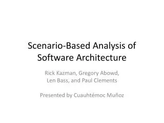
Software Scenario for Control System of Indus-2. R. K. Agrawal, Amit Chauhan, A. M. Gupta,B. Merh, K.Saifee, P. Fatnani, S. Gangopadhyay. Centre For Advanced Technology (CAT), Indore, India. Outline. Overview: About us, Indus-2. Control System Architecture. Software Architecture.

E N D
Software Scenario for Control System of Indus-2 R. K. Agrawal, Amit Chauhan, A. M. Gupta,B. Merh, K.Saifee, P. Fatnani, S. Gangopadhyay Centre For Advanced Technology (CAT), Indore, India ICALEPCS 2005, Geneva
Outline • Overview: About us, Indus-2. • Control System Architecture. • Software Architecture. • Software Components at various Layers. • Present Status. • Conclusion. ICALEPCS 2005, Geneva
Our coordinates (1) ICALEPCS 2005, Geneva
Our Coordinates ICALEPCS 2005, Geneva
About us: Controls Lab Design and Development of Hardware: VME Bus based boards for 18 bit DAC, 16 bit ADC, 500 MHz Timing coincidence, Delay generator, Profi Master/Slave, ramping clock generator , Opto In, Relay Out, CPU ( 68K), Secondary Emission monitor, Ion Gauge controller etc. Software: Embedded: Profi Master/ slave protocol implementation,OS-9 Porting on CPU, Device drivers, Supervisory controller software, Equipment controller software etc. Application Level: PVSS, LabView, Web technologies, Java, MatLab, C++, Database Configuration etc. ICALEPCS 2005, Geneva
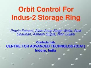
Introduction to Indus-2 20 Mev Microttron Source 450/700 MeV Booster Syncrotron 450 Mev Indus-1 Storage Ring 2.5 Gev Indus-2 Storage Ringunder commissioning ICALEPCS 2005, Geneva
Indus-2 Parameters • Energy 2.5 Gev • Current 300 mAmp. • Circumference 172.4743 meter • Beam Lifetime 18 hours • RF frequency 505.812 MHz • Harmonic number 291 • Bending Magnets 16 ICALEPCS 2005, Geneva
Control SystemArchitecture (1) • Three-layer architecture • User-Interface layer (UI), • Consists of desktop PCs with Windows operating system. • Supervisory Control layer (SC) • Consists of VME bus based CPUs • Supervisory controllers are VME controllers running OS-9. • Equipment Controller Layer (EC). • Consists of VME bus based CPUs • Various Interface Cards DAC,ADC,Digital I/O etc. ICALEPCS 2005, Geneva
Control systemArchitecture (2) ICALEPCS 2005, Geneva
Main Features of Software Technologies • Based on the distributed client server architecture • Employs object-oriented methodology • Commercial SCADA package PVSS-2 at UI • Open architecture • Flexibility in interfacing front-end instruments • Existence Varied standards and adaptability to fast changing hardware and software technologies ICALEPCS 2005, Geneva
Web Clients Database Intranet Machine Application Programs C++ Matlab Java UI Data Acquit ion and operator -interface software Java Application C++ Application Labview PVSS-2 SCADA Communication Protocols TCP/IP API Manager MOD Bus OPC Custom Protocol Front-end Instruments/Equipments SC, DSO, DMM, FG, RGA Software Architecture at Layer-1 ICALEPCS 2005, Geneva
SOFTWARE TECHNOLOGIES AT UI LAYER • PVSS-2 provides interface to standard and custom protocols like GPIB, OLE for Process Control (OPC), TCP/IP custom socket communication, Modbus etc. • Data trending, Alarms, configurations, and data archiving are easily implemented in PVSS. • Labview is also used for data acquisition. • Machine application programs like closed orbit correction are implemented in MATLAB. • PVSS API managers are used for inter-application communication. • The data from all the subsystems will be logged periodically to a Database using the ADO/ODBC interface and information manager from PVSS-2. • Online machine data from the PVSS SCADA can be retrieved from the web-browsers. ICALEPCS 2005, Geneva
Data Flow from SC to SCADA ICALEPCS 2005, Geneva
Communication Protocols • The front-end instruments and equipments to be interfaced to the control system are Supervisory controllers, Digital Storage Oscilloscope (DSO), Digital multi-meter (DMM), Function Generators (FG), Residual Gas Analyzer (RGA), custom power supplies etc. • They have different communication standards like GPIB, OLE for Process Control (OPC),TCP/IP custom socket communication, Modbus etc. ICALEPCS 2005, Geneva
Communication Protocols (Conti.) • Industry standard protocols like OPC and Modbus provide seamless interface of commercial instruments. • For specialized instruments, OPC servers are developed so that they are independent of data- acquisition and operator-interface applications. ICALEPCS 2005, Geneva
TCP/IP Network 68040 CPU Board SOS Socket Process Profi Master Board Profi-Master Aux Process1 Aux. Process2 Optional Mgmt. Board 1 Optional Mgmt. Board 2 Software Architecture at Layer-2 P R O F I B U S ICALEPCS 2005, Geneva
Software Architecture at Layer-2 • PROFIBUS masterprotocol is implemented on Motorola 68040 based MVME-162. • Performs various Profi Services like: • Parameterize and Configuring Slaves, • Maintaining list of live slaves, • Performing cyclic data collection from slaves, • Maintaining Master’s configuration • TCP/IP datagram socket server running at Layer-2 • communicates with GUI program at Layer-1. ICALEPCS 2005, Geneva
68000 CPU Board Profi Slave Board P R O F I B U S P R O F I B U S Profi Slave I/O Proc 3 I/O Proc 2 I/O Proc 1 I/O Proc 4 Analog I/P Board(ADC) Digital O/P Board (Relay) Digital I/P Board(Opto) Analog O/P Board (DAC) Scheme at Layer-3 ICALEPCS 2005, Geneva
Software Architecture at Layer-3 • PROFIBUS Slaveprotocol has been implemented on in-house developed Motorola 68000 based boards. • Real Time operating System OS-9 customized and ported. • It performs functions like: • Collecting Data from various I/O cards , • Receiving and parsing Profi telegrams from master, • Passing the data to master when asked, • Maintaining slave configuration, SAP list etc. ICALEPCS 2005, Geneva
Database System Configuration for Indus-2 • Client/server model • A dedicated database server on the network Relational model: avoids redundancy and prevents inconsistency • Centralized data store • Data Integrity,validity and access control ensured • Data access possible through simple SQL • Periodic backup • WWW access possible ICALEPCS 2005, Geneva
Web Technology in Indus-2 • FAULT INFORMATION MANAGEMENT SYSTEM • INDUS ON-LINE • STORAGE RING STATUS INFORMATION SYSTEM ICALEPCS 2005, Geneva
Web Technology in Indus-2 ICALEPCS 2005, Geneva
Present Status • Catering to data acquisition and control for all sub systems of Indus-2. • 7 SC and 75 EC stations spread in the field. • This system is handling ~10,000 I/O points. • Instruments like DSOs, Spectrum Analyzers, video monitors are also interfaced with the control system. • The various GUI panels, API managers and server programs at SC layer provide a comprehensive machine interface to the users. ICALEPCS 2005, Geneva
Control Room Instrument’s Panel Supervisory Controller Instrument Gallery and Experiment Hall Present Status(2) ICALEPCS 2005, Geneva
Various Panels ICALEPCS 2005, Geneva
Present Status(3) Dipole Magnet Vacuum Chamber Q- Pole Magnet in Field Mapping ICALEPCS 2005, Geneva
Summary • Profi Master/Slave protocol implemented and in use. • Use of PVSS SCADA allowed faster development of UI layer applications. • The various software in the control system are providing the required functionalities. • Web technology is used for status display and fault logging. • The modular software architecture with different standards and communication protocols have been successfully implemented and integrated. • We find this model well suited to the changing requirements of the accelerator control system. ICALEPCS 2005, Geneva
Thank You ! The World is a Global Village Cooperation for Peace and Progress ICALEPCS 2005, Geneva
Data Transfer through Service Access Points (SAP) PROFI Controller FDL User SAP Table SAP NO.1 SAP NO. SAP Data SAP Activate Service RS 485 Link Data Length Activate Service Routine Activate Telegram /SAP parsing Routine SAP NO.2 Location SAP Data SAP Update Service Update Service Routine Data from I/O Devices ICALEPCS 2005, Geneva
Indus-2 Building ICALEPCS 2005, Geneva
Expriment Hall and Equipment Gallary ICALEPCS 2005, Geneva
COMMAND FRAME COMMUNICATION BETWEEN PROFI MASTER AND PROFI SLAVE MASTER SLAVE 1 SLAVE 2 6 8 0 4 0 D P R A M 6 8 0 4 0 D P R A M 6 8 0 4 0 D P R A M 8 0 3 2 0 R A M 8 0 3 2 0 R A M 8 0 3 2 0 R A M COMMAND CYCLE RS 485 LINK MASTER SLAVE 1 SLAVE 2 6 8 0 4 0 D P R A M 6 8 0 4 0 D P R A M 6 8 0 4 0 D P R A M 8 0 3 2 0 R A M 8 0 3 2 0 R A M 8 0 3 2 0 R A M RESPONSE CYCLE RS 485 LINK RESPONSE FRAME Station Response Time : 150 microseconds ICALEPCS 2005, Geneva
Implementation Scheme Implementation PROFI Bus On ISO/OSI Model 68000/68040 based board Running on RTOS OS-9 [ FDL User ] Application Layer Data Link Layer 80320 based board Running on its firmware [ PROFI Controller] Physical Layer Contd…. ICALEPCS 2005, Geneva
Implementation Scheme (cont.) User Interface Ethernet Link VMEbus • Field Management Services : • Reset, set parameters, SAP activation, SAP updation, SAP deactivation, etc. • Data Transfer Services : • SRD and SDN are implemented in this. SC LAYER Profi Controller FDL User 68040-CPU Profi Master Profi Telegrams RS 485 Links EC LAYER Profi Slave Profi Controller FDL User 68000-CPU VMEbus Digital and Analog I/O ICALEPCS 2005, Geneva
INTERRUPT Shared RAM Motorola 68000 BASED PROFI –FDL USER Dallas 80320 BASED PROFI CONTROLLER COMMAND SECTION RESPONSE SECTION RS-485 BUS INTERRUPT COMMUNICATION BETWEEN PROFI-FDL USER and CONTROLLER ICALEPCS 2005, Geneva
PROFI Controller FDL User SAP Table SAP NO.1 SAP NO. SAP Activate Service SAP Data Data Length RS 485 Link Activate Service Routine Activate Telegram /SAP parsing Routine SAP NO.2 Location SAP Update Service SAP Data Update Service Routine Data from I/O Devices DATA TRANSFER THROUGH SERVICE ACCESS POINTS (SAP) ICALEPCS 2005, Geneva
1. Processor Speed : 8 MHz • 2. Interrupt Latency < 6 usec • 3. Task Switching Time < 400 usec • 4. Process Time Slice = 20 msec • Here the Processes run in a Priority –Based Round Robin scheduling manner ICALEPCS 2005, Geneva