Download
1 / 25
260 likes | 444 Views
The LIGO input optics D.B. Tanner, M.A. Arain, A. Lucianetti, R. Martin, V. Quetschke, L.F. Williams, Wan Wu, G. Mueller, and D.H. Reitze University of Florida IO for initial LIGO IO for enhanced LIGO IO for advanced LIGO Supported by NSF grant PHY-0555453. IOO = “input optics”.

E N D
The LIGOinput optics D.B. Tanner, M.A. Arain, A. Lucianetti, R. Martin, V. Quetschke, L.F. Williams, Wan Wu, G. Mueller, and D.H. Reitze University of Florida IO for initial LIGO IO for enhanced LIGO IO for advanced LIGO Supported by NSF grant PHY-0555453 L-V Pisa May 07
IOO = “input optics” L-V Pisa May 07
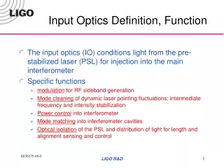
Adv LIGO Input Optics • The Input Optics conditions the light from the pre-stabilized laser, sending it to the main interferometer • Phase modulation • Electro-optic modulators • Interferometer power control • Continuous variable attenuation • Spatially and temporally filter the light • Mode cleaner • Optical isolation + diagnostic signals • Faraday isolator • Mode match into the interferometer • Adaptive beam-expanding telescope L-V Pisa May 07
RF modulators L-V Pisa May 07
Mode cleaner: SOS SOS = small optics suspension. Mirrors are 3 inch diameter, 1 inch thick. Hung by a single loop of 0.0017 inch diameter steel wire. Mirrors have magnets glued to their backs Coils on frame can push, tip, tilt the mirrors. Safety stops all around to catch mirror if the wire breaks. Several did during the 2001 Olympia earthquake. L-V Pisa May 07
Faraday isolator L-V Pisa May 07
Parts installed in vacuum chambers with incredible precision L-V Pisa May 07
HAM 1 L-V Pisa May 07
LIGO, eLIGO, Adv LIGO L-V Pisa May 07
RF Modulation • Requirements: • Amplitude and phase stability: • Amplitude: differential radiation pressure noise due to arm cavity carrier imbalance Dm < (10-9/m)(f/10 Hz)/rtHz • Phase: no direct coupling for DC readout, but possible couplings through auxiliary loops • Rubidium titanyl phosphate (RTP) • Electro-optic response similar to LiNbO3 • low absorption low thermal lensing • In-house design and build • Matching circuit in separate housing • Modified version for eLIGO upgrade Mueller, LIGO T020022 (2002). Mueller, et al., LIGO T020025 (2002). UFGroup, LIGO E060003 (2006). L-V Pisa May 07
eLIGO: 3 frequencies / 1 crystal • Use one crystal but three separate electrodes to apply three different modulation frequencies at once. L-V Pisa May 07
Assembled modulator • Separate the crystal housing from the housing of the electronic circuits to maintain maximum flexibility. L-V Pisa May 07
Modulation index • Measure with 10 Vpp drive, 23.5 & 70 MHz. • m23.5 = 0.29 • m70 = 0.17 L-V Pisa May 07
AdvLIGO: Mach-Zehnder • Modulation architecture needed to eliminate cross products • Mach-Zehnder architecture • Requirement: differential arm motion carrier-sideband phase noise common mode frequency noise: DL ~ 7 x 10-14 m/rHz in 20 – 80 Hz band • Complex (AM/PM) modulation Closed-loop noise suppression TF L-V Pisa May 07
Adv LIGO layout • MZ on the PSL/IO table L-V Pisa May 07
Faraday isolator • Faraday rotator • Two 22.5° TGG-based rotators with a reciprocal 67.5° quartz rotator between • Polarization distortions from the first rotator compensated in the second. • ½ waveplate to set output polarization. • Thermal lens compensation: negative dn/dT material: deuterated potassium dihydrogen phosphate, KD2PO4, or ‘DKDP’). • Calcite wedges or TFP polarizers • Will be used in eLIGO upgrade TGG Crystals Faraday Crystal DKDP Thermal Lens Compensation Polarizer l/2 Polarizer QR H H L-V Pisa May 07
Mechanical design- TFP • TGG and quartz crystals all in large magnet housing • TFP’s on stands, orientation controlled by mechanical design • DKDP compensator on fixed stand • ½ wave plate on CVI vacuum-compatible rotator L-V Pisa May 07
FR CWP l/2 TFP CWP FI set up at LLO L-V Pisa May 07
Faraday Isolator performance Isolation Focal power • Suppression is set by the polarizers. • Calcite wedge polarizer superior to thin film Brewster's polarizer L-V Pisa May 07
Effect of vacuum • Initial vacuum testing reveals drop in isolation ratio under vacuum • from >47 dB to < 30 dB (@100 W) • It’s all temperature • Thermal contact of TGG and housing undergoing re-design • Thermal time constant ~ 45 mins • Isolation recovers with < 1o rotation of waveplate L-V Pisa May 07
Thermal model • Isolation ratio (dB) • -> FI transmission T • -> Polarization angle, from T ~ cos2(q) around q = 900 • -> Verdet constant vs. time, from V = q/(B*L) • -> Temperature from known dV/dT • Then the time dependence fits to T(t) = To + DT * [1-exp(-t/t)] • t ~ 50-100 mins L-V Pisa May 07
Marginal PRC • Baseline Design: • Flat-Flat Recycling Cavities ~10m 4km • Thermal Lenses in ITMs: • Generated higher order modes • resonantly enhanced in flat/flat cavity • [ increased losses • [ increased noise L-V Pisa May 07
Stable recycling cavities • Move beam expanding/reducing telescopes into recycling cavities to create stable and flexible recycling cavities (under LSC review) • suppress higher order modes • maintain mode matching between arm cavity mode and recycling cavities L-V Pisa May 07
Stable PRC layout • Power recycling cavity: • fprc = (k + 1/2)c/2Lprc(k = 0,1,2, ...) • Factor of 1/2 occurs because the • carrier is resonant in the arms; • sidebands are not • Input mode cleaner • fimc = nc /2Limc (n = 1,2,3, …) • Signal recyling cavity • fsrc= (p + df/2p)c/2 Lsrc (p = 1, 2, …) • Allows 9.3996 & 46.9979 MHz • See “Optical Layout for Advanced LIGO,” D. Coyne, LIGO- • T010076-010D (7/1/2001) L-V Pisa May 07
HAMs 2 and 3, with SPRC • It does all fit, though HAM 2 will be full • Beam injection TBD • IO for eLIGO: • Under construction • IO for adv LIGO: • PDR underway L-V Pisa May 07