Download
1 / 23
230 likes | 408 Views
Explore the functions, protocols, and advantages of digital system buses for seamless data transfer between modules in a digital system. Learn about synchronous and asynchronous buses, transaction cycles, speeds, and architectures.

E N D
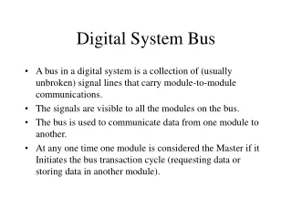
Digital System Bus • A bus in a digital system is a collection of (usually unbroken) signal lines that carry module-to-module communications. • The signals are visible to all the modules on the bus. • The bus is used to communicate data from one module to another. • At any one time one module is considered the Master if it Initiates the bus transaction cycle (requesting data or storing data in another module).
Example of Buses • ISA (Industry Standard Architecture): Used to equip 486 based computers. Now being phased out for desktops as considered too slow. • VL-BUS or VESA Bus: Introduced to speed up graphic display for ISA based computers. • PCI (Peripheral Components Interconnect): This is the standard in desktop today. The PCI bus also supports Plug and Play. • VME (Versatile Modular Eurocard): Mainly used in special applications and in industrial systems.
Bus Functions • Bus lines can be split into three groups Address, data and commands: • Bus transfer control lines: (also called `data handshake lines’) control timing of information transfers on the bus. These start and stop bus transactions regardless of transaction type. • Arbitration lines: guarantee that only one module at a time transmits on the bus i.e. they prevent clashes by arbitrating which module gains access to the bus. The winning module will be called the BUS MASTER. Other modules are BUS SLAVES.
Bus Transaction Protocols • Also called the Bus Handshake. • A bus transfer protocol is just a convention for data transmission that involves a sequence of actions according to some timing specification. • There are three classes of bus transfer protocols: • SYNCHRONOUS - clocked transfer with one clock period per transfer. • ASYNCHRONOUS - unclocked transfer. • SEMI-SYNCHRONOUS - clocked-transfer with more than one clock period per transfer.
Synchronous Buses • Have a clock signal which is distributed on the bus to synchronise all modules to a common time base. • The typical MASTER/SLAVE structure • Read/Write timing for a system with clock rising edge starting transaction and clock falling edge ending transaction.
Signal Preparation and timing with respect to Clock • Signal skew delay is the change in the relative timing of signals on a bus due to differences in propagation delays, signal paths, gate delays and logic thresholds: • Bus protocol must incorporate set-up and hold times that are long enough to satisfy the maximum of address and data requirements
Synchronous Bus Speeds • Effects that limit bus speed are: • setup time of data and control signals before clock : — TSetup • address decode delay : — TDecode • skew time of address and data signals relative to a rising and relative to a falling clock edge : — 2 TSkew • hold time of data at a buffer input : — TH • round-trip TP for READ cycle. • To calculate the bus cycle time, we must add these to the maximum response time of the slaves plus the internal delay of the master between transactions. • Bus cycle time, TCYC, cannot be smaller than the sum
Read Cycle Round-Trip Time • For example if a MASTER generates clock: suppose the master drives the clock inactive at the end of the cycle. • Tp later, slave sees clock deactivate and stops driving the data lines. • data will be stable at the masters input buffers one Tp after the slave stops driving the data lines. This time delay has to be accounted for when calculating bus cycles
Advantages/Disadvantages • Advantages • Simplicity - single line control • Generally lead to fastest possible transactions since has minimal extra delay overheads • Disadvantages • Bus length is usually short because of the requirement of distributing the clock. • System clock rate must be set to handle slowest slave on bus.
Asynchronous Buses • Overcomes the disadvantages of a synchronous bus but at expense of complexity and reduced speed. • The safest and most common asynchronous bus is the Fully Interlocked, Asynchronous Bus. • An example is the VME (Versatile Modular Eurocard) bus • Requires two control signals, one from the MASTER and one from the SLAVE.
Hold Times for Slaves • Hold times for the SLAVE can be guaranteed • in a WRITE cycle by the SLAVE delaying its rising edge, and • in READ cycle by the MASTER delaying its falling edge for the master’s hold requirements. • For a READ the SLAVE rising edge is delayed to satisfy the slave’s address hold time requirements.
Asynchronous Bus Transaction Speed • Minimum cycle time for READ operation must account for • skew and setup time of address at the slave • address decode at the slave • skew and hold time of data returned by slave • two round-trip propagation delays of MASTER and SLAVE signals • The purpose of the second round-trip propagation delay is to convey completion information that is not bounded in advance (as is the case in the synchronous bus). • Asynchronous buses can be VERY LONG buses.
Semisynchronous Buses • Wait-State Protocols • Combines advantages of synchronous and asynchronous buses. • An example is the PC AT (ISA) bus. • Requires 2 control signals: CLOCK from master and WAIT from slave.
Wait State Transactions • If the slave is fast enough to respond in one clock cycle it does not raise WAIT and the bus behaves like a synchronous one. • If the slave cannot respond in one cycle it raises WAIT and the master waits. Slave drops WAIT when it can respond and the master completes the transaction as for the synchronous protocol. • Restricts bus length due to requirement that WAIT must be asserted within a fixed period of time.
Bus Arbitration Protocols • Bus Arbitration protocols decide bus mastership and hence access when more than one module is requesting the bus. • Several arbitration methods, and we look at two here: • 2-Wire Daisy Chain Bus Arbitration • 3-Wire Daisy Chain ...
2-Wire Daisy Chain • Modules close to bus arbiter have higher priority than modules further away. • Simple 2-wire systems must be implemented with care!
Example of 2-Wire Daisy Chain Failure • Consider the following sequence: • M2 requests bus at a time when M1 does not • Arbiter senses Request, issues Grant • M1 passes Grant to M2 • M2 accepts Grant, blocks Gout to M3, and takes bus then shortly after • M1 wants bus, sees Grant and takes bus!!
Example of 2-Wire Daisy Chain Failure • MORAL: • Looking only at Grant is not adequate. • Modules must inspect both Request and Grant lines to determine if a lower-priority module is actively controlling bus. Grant H and Request H define this condition. • One possible safe arbitration scheme for a 2-wire daisy chain is: • Module must see grant go high after it’s request is raised. • Grant not passed to lower modules if no request from them
3-Wire Daisy Chain • BUS BUSY is asserted by module which has control of bus • Modules wanting bus raise the REQUEST line • ARBITER issues GRANT when REQUEST active and BUS BUSY inactive • Modules not requesting pass GRANT down chain • Module takes bus when • it has local request pending • BUS BUSY is inactive • it detects rising edge of GRANT
Daisy Chain Summary • The 3-wire protocol has higher reliability than the 2-wire protocol - inactive BUS BUSY and the rising edge of GRANT must be seen before a module will attempt to take the bus. • The 3-wire protocol is thus less sensitive to glitches. The 3-wire scheme or variations of it are used for most high performance buses. • The asynchronous nature of arbitration protocols means that none are completely safe. The reason for this surprising result is that the asynchronous arbitration signals must be recognised by synchronous devices. When set-up times are not met, the phenomenon of metastable states can cause failure.