Download
1 / 32
320 likes | 376 Views
This comprehensive guide covers topics such as MOSFET voltage-current equations, ID-VD characteristics, gate sizing, scaling laws, and FET performance optimization. It discusses key concepts related to FET scaling, NMOS inverters, logic gates, and device design considerations. The text explores fundamental principles, problem-solving techniques, and design verification steps for efficient FET operation.

E N D
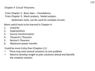
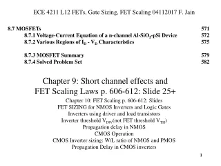
ECE 4211 L12 FETs, Gate Sizing, FET Scaling 04112017 F. Jain 8.7 MOSFETs 571 8.7.1 Voltage-Current Equation of a n-channel Al-SiO2-pSi Device 572 8.7.2 Various Regions of ID - VD Characteristics 575 8.7.3 MOSFET Summary 579 8.7.4 Solved Problem Set 582 Chapter 9: Short channel effects and FET Scaling Laws p. 606-612: Slide 25+ Chapter 10: FET Scaling p. 606-612: Slides FET SIZING for NMOS Inverters and Logic Gates Inverters using driver and load transistors Inverter threshold VINV(not FET threshold VTH) Propagation delay in NMOS CMOS Operation CMOS Inverter sizing: W/L ratio of NMOS and PMOS Propagation Delay in CMOS inverters 1
2011 ITRS equivalent scaling process technologies, including high mobility channel materials, high-k gate dielectrics, and novel device structures . 2
N-channel n-FETs and p-channel p-FETs Fig. 1b, 1c . Fig. 1b Fig. 1c p-channel comprise of mobile holes. It is induced on p-Si surface when gate voltage of negative polarity in magnitude Vg>VTH N-channel comprise of mobile electrons. It is induced on p-Si surface when gate voltage Vg>VTH 3
8.5.1 Voltage-Current Equation of a n-channel Al-SiO2-pSi N-channel FET, Fig. 1(A) page 572 The work function difference increases as ND is increased. 4
Fig. 4, p 576 Finite slope in saturation part due to channel length modulation -‘L’ shrinks -Id increases - (Z/L increases )
Fig. 5 Sub-threshold conduction Sub threshold figure of merit expresses the required reduction in gate voltage VGS to decrease the leakage drain current ID by an order of magnitude. Page 597 Fig. 5. ID-VG or transfer characteristics of an n-channel FET(Al-SiO2-pSi).
Background (Sections 9.1-9.6) 9.1 Short-Channel Effects 587 9.2 Mobility Degradation 590 9.3 Subthreshold Conduction 595 9.4 Subthreshold Figure of Merit 597 9.5 High-field Effects 599 9.6 Punch-through 601 Fig.4, page 600 High Field Effects Fig. 1a. Channel pinch off, p 587
FETs Chapter10.1(page 637) FETs Symbols for enhancement type and depletion type
FET Characteristics N-FET enhancement N-FET Depletion p-FET enhancement p-FET depletion
FET Scaling Laws (p.606) Constant electric field (CE): The central point is to maintain electric field constant in the gate oxide and in the depletion region, after scaling down the dimensions. Thus, L, W, tox, are reduced by a factor k, voltages are reduced by the same factor k, and substrate doping is increased by k. 1. Linear dimensions are reduced by a factor k: L, W, TOX are divided by k (k>l) to obtain scaled-down values. e.g. L' = L/k, W' = W/k, T'OX = TOX/k (1) 2. Voltages are reduced by k. e.g. V'DS = VDS/k, V'GS = VGS/k (2) 3. Substrate doping is increased by k. e.g. N'A = NA* k (3) The applied voltages are reduced to maintain electric field strengths as in the case of long-channel or un-scaled devices. In case of substrate doping, the rationale is to keep the depletion width x'p = xp/k
Constant Voltage (CV) and Quasi Constant Voltage QCV: p.609 k > > 1
1) The scaled-down potentials/voltages ϕ' = ϕ/k here, k >1 2) The scaled-down dimensions (x',y',z') = (x,y,z)/λ here, λ >1 3)The scaled-down concentrations (n',p',N'D,N'A) = (n,p,ND,NA)/δ It will be shown, following Baccarani et al that δ = k/λ2, if potential distribution shapes are to be preserved in scaled- down devices. Design steps using Generalized Scaling, p613 Generalized scaling (GS) p.610 1. Find dimensional scaling l from existing channel dimensions and desired scaled- down 2. Using processing parameters, determine threshold variation DVTH Determine VTH (=~4 DVTH) and VDD (VDD ~4*VTH) 3. Find the voltage scaling factor k 4. Compute the scaling factor d for doping.
Finding DVTH Dopant density variation (due to implant or in substrrate) Oxide or gate insulator thickness variation Oxide dielectric constant variation in thin films of 1-2nm Channel width and length variation, Oxide charge density variation
Verification of scaled-down design 1. Is the oxide thickness realistic in terms of gate leakage current? 2. Is supply voltage and threshold realistic in terms of source to drain tunneling? 3. Is the device to device fluctuation in a die and in dies in a wafer acceptable? 4. Is the drive current acceptable? Is the ID-VG and ID-VD characteristics ok in terms of fan-in and fan-out and logic noise margins?
Chapter 10 NMOS Inverter Fig. 1, p. 638
10.2.2 Device sizing in static (or ratioed) gates/networks Eq. (8) p. 642
VOUT VDD VINV Wpd increasing VINV VDD VIN Inverter Gain Fig. 6. Output-Input voltage characteristics a a function of Wpd The slope of the voltage transfer characteristics
10.2.3 Dynamic logic gates/networks Fig. 7. A dynamic or two-phase ratio-less inverter
Fig. 13, p.649 Layout of NMOS Inverter Fig. 10. (b) Schematic and (b) layout an NMOS inverter.
Sizing of FETs in a logic gate (p.647) Fig. 11. NMOS gate with W/L ratios of various FETs.
Circuit Model Fig. 14(b) Intrinsic model showing capacitances. Fig. 14a. Capacitances Page 650
Capacitances are computed to find propagation delay(p. 651-660)
p.660 CMOS Inverter p.661 Fig. 21 Voltage transfer characteristic
Fig. 33. Latch up in CMOS inverter (p672) Fig. 26. Sizing of CMOS transistors (p 668)
Fig. 27 Sizing of 2-input NOR 2-input NAND CMOS inverter (p668)