Download
1 / 17
170 likes | 189 Views
Learn about Coherent Diffraction Radiation, its advantages, impact parameter, and simulation studies for beam diagnostics. Explore CDR setup, power generation, and experimental observations at CERN.

E N D
Coherent Diffraction Radiation (CDR) for short bunch length diagnostics Pavel Karataev, Grahame Blair, Stewart Boogert, Gary Boorman, Konstantin Lekomtsev (1st year PhD student), MaximilianMicheler (2nd year PhD sudent) Robert Ainsworth (4th year MSci summer student) John Adams Institute at Royal Holloway, University of London Nicolas Chritin, Roberto Corsini, Thibaut Lefevre, Patrick Lelong CERN CLIC Instrumentation Workshop, June 2 –3, 2009
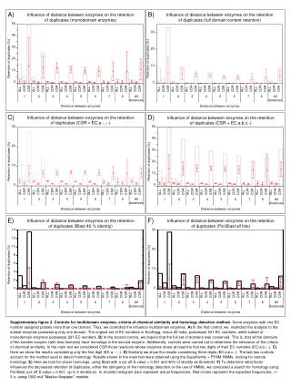
Coherent Optical Transition Radiation Observation at LCLS H. Loos, et al., SLAC-pub-13395
COTR spectra • The form of the coherent spectrum fluctuates from shot to short • Existence of spikes in the spectrum suggests that there are a few microbunches in the longitudinal particle distribution • The coherent part of the OTR intensity could be much higher than the incoherent one
Advantages It appears when a charged particle moves in the vicinity of a medium For our setup at CTF3, h ≈ 15 mm << = 1175mm for = 235 and = 5mm. • - observation wavelength = E/mc2 – Lorentz - factor Impact parameter, h, – the shortest distance between the target and the particle trajectory
Advantages • Non-invasive method • Instantaneous emission • Single shot measurement option • Large emission angles (0 ~ 1800) • Single electron spectrum is predictable • Relatively inexpensive and easy in use • No theoretical resolution limit • Gives information about the longitudinal profile
Coherent radiation • Coherent radiation: S(ω) = [Ne+Ne (Ne-1)F(ω)] Se(ω) • S(ω) is the signal, known from the experiment • this can be obtained by using an interferometer • Se(ω) is the single electron radiation, which should be predictable form theory • Ne is the number of electrons, known from the experiment • F(ω) is the longitudinal bunch form factor, which is the measurement purpose. • the bunch form factor is just the Fourier transform of the spatial charge distribution in space • the longitudinal bunch profile can therefore be reconstructed using Kramers-Kronig relation Incoherent part Coherent part
Simulation studies • Diffraction radiation spectra with • needed in the de-convolution of the spectral information (see previous slide) • S(ω) = Ne2 F(ω) Se(ω) • Intensity dependence on impact parameter (γ=235): • at a considerable distance from the beam the signal level is still high • non-invasive measurements • Diffraction radiation spectra for different beam energies • zero-impact parameter • for higher energies the intensity increases
Power generated by CDR Average power emitted per train by DR for DXP19 and impact parameter (h=10 mm): • For a 2mm Gaussian beam the energy emitted into the detector is 3.6x10^-9 J/bunch • The average power per train is 5.5W and 11.0W for 1.5GHz and 3GHZ operation • For 2.5 x 10^10 electrons per bunch the energy contribution per electron is 0.9eV
CDR setup @ CTF3 CDR setup: • Installed the vacuum hardware in the CRM line at CTF3 • The technical drawing of the CRM line (bottom right) shows the CDR setup (11) just in front of the OTR screen (7)
CDR Setup in 2008 Vacuum manipulator for target rotation and translation OTR screen for target reference position CDR target within six-way cross BPM (not shown in picture) for beam position and charge readings Schottky barrier diode detector connected to DAQ
SBD detector As a detector we used an Ultra-fast Schottky Barrier Diode with the following parameters
CSR and CDR signal Signals observed at CTF3 in 2008: • Signal of CDR and CSR including the BPM current reading • Variation of the SBD signal for CSR and CDR suggests a bunch length variation along the train CDR signal: CSR signal:
Observation of CDR signal CDR and CSR signal dependences (horizontal polarization): • Checked the signal level depending on the target position and orientation • Good agreement with expectation but some distortion (CDR, CSR) and offset (CSR) • Distortion can be explained by background caused upstream (wake-fields, CSR, etc.) • Offset can be explained by the offset beam in the bending magnet Diffraction radiation: Synchrotron radiation:
Current system 2009 Upgrades: • Installed the interferometer (right hand picture) • Photo diode (incl. beam splitter) in the OTR optical line installed (left hand picture) for fast charge measurements • OTR light is linearly proportional to the bunch charge
Summary Status of experiment at CERN: • Installed the update of the system in the CRM line • Interferometer • Photodiode in OTR optical line • Currently experiencing some problems • Did not have sufficient beam time to find interference with CDR (dedicated beam time) • Cabling between the photo diode and the DAQ • Still debugging the system and understanding the new setup Plans: • Continue debugging and understanding the system • Interferometric measurements • Reconstruction of the longitudinal bunch shape using Kramers-Kronig method (on going) • Calculate interferometer splitter efficiencies (on going)
Future upgrade Insert a second target to cut the background off June 3, 2009 17