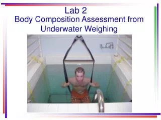

Lab 2 Alignment
E N D
Presentation Transcript
Definition of alignment Placing the optical axis of each element on the optical axis of the system This implies defining the optical axis of the system and finding the optical axes of the elements For a finite conjugate system the optical axis is the line joining the object and image For an infinite conjugate system the optical axis is a line between the object/image and an autocollimating flat
System optical axis Finite conjugate system Infinite conjugate system
Motivation for alignment Alignment is really a two step process - A first order step using two degrees of freedom A second step to zero out aberrations using remaining DoF If only the first step done, light is focused at the correct location but the image quality will be poor, in general The second step must be done while holding the first order properties constant Now we will look at a few definitions of DoF of verious optical elements Then we’ll look at some examples
Alignment properties of elements Point – theoretical construct – defined by 3 position coordinates, x, y, z, or three degrees of freedom Ball or sphere – physical realization of a point Defined by location of center, x, y, z and radius, r The center is an intrinsic property of a sphere, the radius extrinsic A sphere has no axis; repeat, no intrinsic axis Spherical mirror – section of a ball – a center of curvature and a radius There is no optical axis, only a mechanical axis
Alignment properties of elements, con’t Line – theoretical construct – defined by 2 points at arbitrary distances along the line, say, x1, y1 and x2, y2, or 1 point, x1, y1 and 2 angles, alpha and beta, or 4 degrees of freedom Plane mirror – defines a line as a normal to the surface, 2 angles Cylinder or rod – is a physical realization defined by a pair of points or a point and a pair of angles plus a radius about the line or axis Cylindrical mirror – defined by an axis or line and a radius Again, the four points are intrinsic, and the radius extrinsic
Alignment properties of elements, con’t The axis of a lens is defined by the line joining the centers of curvature This can be the physical CoC or the optically apparent CoC There are four intrinsic degrees of freedom defined, and extrinsic radii and thicknesses Rotation about the optical axis is undefined Physical center of curvature Optical center of curvature
1:1 relay example Biconvex lens with 100 mm efl used at 1:1 conjugates – Lab 1 If perfectly aligned and used at full aperture has 3.5 waves p-v of spherical aberration If the lens is decentered just 2 μm we found the image moves 4 μm To restore the image position the lens must be tilted almost 6 degrees and this introduces 10 waves p-v of astigmatism Physical CoC is 10 mm off-axis Optical CoC is 4.8 mm off-axis Holding CoC to 10 or 20 μm results in no aberrations
f/5 objective in autocollimation 100 mm efl achromatic objective in autocollimation off a plane mirror If perfectly aligned the reflected wavefront is .6 waves p-v SA3 mostly Tilt about 2 ° and decenter lens to keep image on top of object ~.34 mm
f/5 objective, con’t Now 2.75 waves p-v, mostly astigmatism, an off-axis aberration Physical CoC are off axis by 4.4 and 2.2 mm Distance from focus to vertex is 34.6 mm
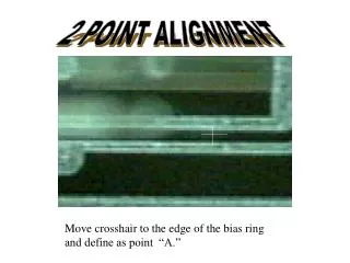
Alignment of objective Insert lens in front of plane mirror Find autocollimated image, reflection from far surface of lens Adjust tilt and decenter of lens, and tilt of plane mirror until both image and far surface reflection are centered when PSM moved along straightedge Plane mirror will be perpendicular to table top and straightedge, and lens used in center of field
Use alignment telescope The alignment telescope is a precision instrument for the alignment of objects on a reference line defined by the line of sight, or optical axis of the telescope Alignment telescope works like PSM except it focuses along its axis Its near focus is about .5 m in front of the objective, far at infinity Return reflection is a set of concentric rings X, y adjustments will have to be made with the hardware The alignment telescope will adjust in angle
Alignment Telescope • The alignment telescope is a precision instrument for the alignment of objects on a reference line defined by the optical axis of the telescope
Alignment Telescope • Determine optical axis • Rotate telescope in holder to ensure telescope is calibrated • Center the target at position 1 using the reticle • Move target to position 2 • Note which way the crosshairs moved • Using bottom and left knobs, move the reticle half the distance • Repeat above 2 steps until the reticle doesn’t move