Download
1 / 28
290 likes | 535 Views
ADJUSTABLE TABLE TOP FOR INJECTION MOULDING MACHINE. Presented by, rahul k.h ramesh.m sajal k.a shajeer m.k

E N D
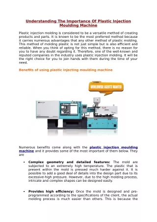
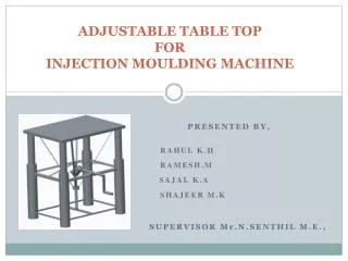
ADJUSTABLE TABLE TOP FOR INJECTION MOULDING MACHINE Presented by, rahul k.h ramesh.m sajal k.a shajeer m.k SUPERVISOR Mr.n.senthil m.e.,
CONTENTS • Introduction • Objective • Methodology • Design and Construction • Bill of material • Fabrication • Working principle • Cost Estimation • Advantages and Disadvantages • Application • Conclusion & Future scope
INTRODUCTION Our project is totally designed for carrying and lifting heavy objects in industries as well as where ever it needs. It is purely operated on mechanical devices such as gears, screw threads; bearing etc. hence it does not use any electrical energy or hydraulic energy. Also we fabricate this project with sheet metal hence the total weight of the project is reduced. By applying simple mechanism it also reduces human effort. It produces high torque by a bevel gear assembly so we can lift heavy objects with less effort. Not like other adjustable table our design provides variable height order. We designed it for holding a injection molding machine based on the industrial requirements but our ultimate aim is to use this table for any work.
BEVEL GEAR • Bevel gears are gears where the axes of the two shafts intersect and the tooth-bearing faces of the gears themselves are conically shaped. • Bevel gears are most often mounted on shafts that are 90 degrees apart, but can be designed to work at other angles as well. • The pitch surface of bevel gears is a cone. Two important concepts in gearing are pitch surface and pitch angle. • The pitch surface of a gear is the imaginary toothless surface that you would have by averaging out the peaks and valleys of the individual teeth. • The pitch surface of an ordinary gear is the shape of a cylinder. • The pitch angle of a gear is the angle between the face of the pitch surface and the axis. • The most familiar kinds of bevel gears have pitch angles of less than 90 degrees and therefore are cone-shaped. This type of bevel gear is called external because the gear teeth point outward.
TYPES TYPES OF BEVEL GEARS Straight bevel gear Spiral bevel gear Zerol bevel gear Hypoid bevel gear Straight bevel gear • It have conical pitch surface and teeth are straight and tapering towards apex. Spiral bevel gear • Ithas curved teeth at an angle allowing tooth contact to be gradual and smooth.
Zerol bevel gear They are very similar to a bevel gear only exception is the teeth are curved: the ends of each tooth are coplanar with the axis, but the middle of each tooth is swept circumferentially around the gear. Zerol bevel gears can be thought of as spiral bevel gears (which also have curved teeth) but with a spiral angle of zero (so the ends of the teeth align with the axis). Hypoid bevel gear They are similar to spiral bevel but the pitch surfaces are hyperbolic and not conical. Pinion can be offset above, or below, the gear centre, thus allowing larger pinion diameter, and longer life and smoother mesh, with additional ratios e.g., 6:1, 8:1, 10:1.
BEARINGS Bearings are very easy to use, which makes their range of uses very broad. They are used in the rotating parts of many devices, beginning with household appliances such as vacuum cleaners, refrigerators and air conditioners and going on to include automobiles, railway cars, aircraft, construction equipment, adjustable table and machine tools as well as large machinery and equipment. Abearing is a machine element that constrains relative motion and reduces friction between moving parts to only the desired motion. The design of the bearing may, for example, provide for free linear movement of the moving part or for free rotation around a fixed axis or, it may prevent a motion by controlling the vectors of normal forces that bear on the moving parts.
OBJECTIVES • This Project is about Mechanically adjustable table top for Injection Moulding machine. • Injection moulding machines are manufactured in such a way that it should withstand sudden loads. • For this reason it is necessary to support the machine using any table that can be mounted under the machine. • It will be easier if such tables are made adjustable as for the need. • Here the table of our idea has a height adjuster fitted to it, such that the height can be varied for different altitudes.
METHODOLOGY DESIGNING OF ADJUSTABLE TABLE MATERIAL SELECTION FABRICATION OF THE TABLE ASSEMBLING THE PARTS ANALYSING THE PROJECT FINAL ADJUSTABLE TABLE SETUP
DESIGN OF BEVEL GEAR In our project we are using a straight bevel gear and using pinion in input shaft for increasing the torque. Straight bevel gears are the simplest form of bevel gears. Contact on the driven gear begins at the top of the tooth and progresses toward the root. They have teeth which are straight and tapered which, if extended inward, would intersect in a common point at the axis. Pinion torque is a convenient criterion for approximate rating of bevel gears, requiring conversion from power to torque by the relation: TP = 63 000 P nP TP = 9550 P nP
DIAGRAM OF BEVEL GEAR BEVEL GEAR
DESIGN OF SCREW THREAD • In our project we are using a right hand standard thread; it will be useful for retaining table position in a fixed state. • Torque = 145 x d3 (for inch series), where Torque is in-lbs. and d is Diameter in inches • Torque = 0.001 x d3 (for metric series), where Torque is Nm and d is diameter in mm • Since it has larger stress areas the bolts are stronger in tension • Their larger minor diameters develop higher torsional and transverse shear strengths • They can tap better in thin walled members • With their smaller helix angle, they permit closer adjustment accuracy
FABRICATION • The sheet metal is first fabricated into the upper part of the table for required dimensions. • Then the hollow pipe made of cast iron is used for the support at four ends of the table. • The support is joined with the table by means of welding. • The table and its support is assemble within the another hollow cylindrical shaft which is useful for sliding while increasing the height of the table. • Now the screw thread shaft is welded with the cross support at mid position. • At the top end of the screw thread, bevel gear is connected with slot key.
FABRICATION • The bevel pinion is attached normal to the gear and it is connected with the support by means of bearing and the other end is connected with the hand wheel. • Then the nut is screwed to the thread and this will connected to the table. This gives the relative motion to the table.
WORKING PRINCIPLE When the hand wheel is rotated either in clockwise or anti-clockwise direction, it transmits the rotation to the screw thread through the bevel gear. The bevel gear is used to transmit the rotation of hand wheel to the screw thread by 90 degree. When the screw thread rotating then the nut screwed with thread starts moving in upward or downward direction with respect to the direction of rotation of the hand wheel. If the nut moves in vertical axis then the table also moves in vertical direction with respect to movement of nut either moving upward or downward.
WORKING PRINCIPLE This movement is possible by proving four supports between the nut and the table. It provides a rigid support between nut and table hence it holds the injection moulding machine at constant height unless we changing the height. SIDE VIEW OF THE TABLE
ADVANTAGE • Total weight of the table is less when compared to the conventional one • Low maintenance • Hand rotation is feeling effortless due to the presence of bearings. • Low cost, because the table made of sheet metal. • Simple in construction • There is no need for an electric power or any other hydraulic power.
DISADVANTAGE • It is difficult to lift heavy weight because of manual operation • Lubrication of a table is occur • Noise may be produced
APPLICATION • It is used in industries to lift heavy materials or machines in ease. • This mechanism may also be applied in art tables. • It is also used in dams. • These adjustable tables are very much useful in medical field for doing operations by various heights. • If this table is slightly modified then it is used as adjustable wheel chair for physically challenged people.
CONCLUSION & FUTURE SCOPE The table is specifically designed for doing industrial work but as your needs change this table could be an all-purpose utility table. Its large size and smooth surface make it ideal for any application. The highlight feature however is the height adjustment which allows the table to adjust to any size The table meets the industry’s specifications about being a sturdy non-electric, mechanical table. It improves upon previous year’s designs because (1) It is not made out of PVC and more stable. (2) It does not require electricity. (3) It allows for more leg room. All of these changes have come together to make an excellent table for industrial use.
REFERENCES • Hydraulic Scissor Lift. Northern Tool + Equipment. Web. 2 Mar. 2011. • A survey of static and dynamic work postures of operating room staff I.J Kant 1 , L C G M de Jong 2, M van Rijssen-Moll 3 , and P J A Borm 11Department of Occupational and Environmental Medicine and Toxicology Int Arch 1991 6 l 493-42 R • Serway, Raymond A. and Jewett Jr, John W. Physics for Scientists and Engineers 6th Ed. Thomson Brooks/Cole. Belmont, CA. 2004. p. 132. • Hibbeler, R. C. Statics and Mechanics of Materials. Pearson Prentice Hall. 2004. p. 743