Download
1 / 16
220 likes | 541 Views
X-ray light source by inverse Compton scattering of CSR. FLS2012 2012. Mar. 6 Miho Shimada High Energy Research Accelerator Organization, KEK. Inverse Compton scattering of CSR ( CSR-ICS ). Hard X-ray and gamma-ray of laser Compton scattering is planned at the Compact ERL. .

E N D
X-ray light source by inverse Compton scattering of CSR FLS2012 2012. Mar. 6 Miho Shimada High Energy Research Accelerator Organization, KEK
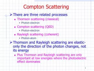
Inverse Compton scattering of CSR(CSR-ICS) Hard X-ray and gamma-ray of laser Compton scattering is planned at the Compact ERL. Photon energy due to inverse Compton scattering Head-on collision CSR-ICS is proposed as a soft X-ray light source at the compact ERL. CSR - ICS laser- ICS CSR is reflected at a mirror and collides with the following electron bunch. M. Shimada and R. Hajima, PRSTAB 13, 100701,(2010)
CSR-ICS at the Compact ERL X-ray expected by the inverse Compton scattering of cERL Corurtesy S. Adachi This area is expected at the cERL
Proposals of the ICSof CSR and CDR N. Sei et al, APEX 1, 087003,(2008) A. P. Porylitsyn et al, PRE 60, 2272,(1999) N. Sei and T. Takahashi, APEX 3, 052401,(2010) A. Aryshev et al, IPAC’10, 196,(2010) • It’s proposed as a real timeTHz Spectroscopy. • THz is converted to visible region. • Flux is very small. • ICS of Coherent Diffraction Radiation • Compact X-ray light source.
Optics 1: Magic mirrorscheme for white light source I S. Kimura et al, Infrared Phys. & Tech 49, 147,(2006) The spot size is assumed to be the same with that of the transverse beam size, which is estimated with betatron and dispersion function. The transverse beam size is smaller than the wavelength of CSR. Electron Beam 200 MeV, 77 pC Acceptance angle of magic mirror 300 mrad [H] x 20 mrad [V] Transverse electron beam size 70 um [H] x 30 um[V]
Magic mirror scheme for white light source II Example: Electron charge : 77pC/bunch Electron energy: 200 MeV, Bunch length : 100 fs CSR (190mm) : 3 x 10¹⁴phs/pulse 10%BW ,4 x 1023phs/s 10%BW (1.3 GHz) X-rays (4 keV) : 5 x 10³phs/pulse 10%BW ,6 x 1012phs/s 10%BW (1.3 GHz) Scattered Photons : 4 x 10⁵phs/pulse 100%BW, 5 x 10¹⁴phs/s 100%BW (1.3 GHz) Pulse duration : 100 fs • Pulse duration of CSR becomes longer because of narrow bandwidth. • Timing jitter should be smaller than the pulse width of CSR. • The cutoff effect is ignored..
Optics 2 : Optical Cavity scheme for narrow bandwidth ICS by an external laser CSR - ICS • Incoherent stacking because the fluctuation of longitudinal position (a few hundreds um) is larger than wavelength of CSR. • Electron bunch emits CSR inside a cavity. • Four mirrors is necessary for two focus points. One is for collection of CSR and another is collision point. • Coherent stacking • External laser is injected from outside a cavity. It passes though a multilayered mirror with low transmittance. • Two mirrors are enough for single focus point. E.R.Crosson et al, Rev. Sci. Instrum. 70, p.4 (1999) Pcav:Power in a cavity, Pin:Input power, R: Reflectance, T:Transmittance, n:Number of mirrors In both cases, pulse power is stacked by 1000 times with reflectivity of mirrors99.97%.
Timing jitter in cERL Layout of a 1-loop ERL Shift of arrival time caused by RF amplitude error *jitter of arrival time is shorter than error of injection time because it is compensated by the error of RF phase. N. Nakamura,Proceedings of IPAC 10, p.2317-2319
Wavelength of CSR for pulse stacking in an optical cavity Total radiation power:P(k) Coherent Incoherent P(k) : Total radiation power N : Number of electron p(k) : Radiation power per an electron r(z) : Longitudinal electron density distribution F(k) : Form factor Gaussian beam with bunch length sz Wavelength of CSR stacked in an optical cavity is chose as follows,
Mode matching Acceptance angle is limited for Mode matching Acceptance angle Q is determined to satisfy the mode matching.
Optimization of collision area : 1 • Half cycle of CSR is destroyed by an narrow band mirror. In the case of bandwidth Δλ/λ, pulse duration of CSR is lengthened by a factor 1/(Δλ/λ).
Optimization of collision area : 2 • CSR in optical cavity is assumed to be Gaussian beam. • Hour glass effect is considered at the collision. Beam size w(z) of Gaussian beam Small zR: small spot size is easy to spread zR<λNc,Nxis independent to zR. • The Rayleigh length is zR=λNc, • to minimize the effect of the timing jitter of electron bunches. • to avoid the non-linear effects.
High reflectivity mirror In the wavelength range of a few 10 um ~a few 100 um, • Reflectivity of metal is lower than 98 %. • It is difficult to fabricate multilayered mirror with larger than 99% reflectivity by conventional method. Development of high reflectivity mirror for terahertz region M.Tecimer et al, PRSTAB 13, 030703,(2010) • Stacking up photonic crystal separated by vacuum layer. • Bandwidth is narrow at the higher order wavelength. • Wavelength, which depends on thickness of the layers, is controllable without losing the high-reflectivity.
X-ray at 60-200 MeVERL • Number of photons of X-ray (b.w.10%) • Number of photons per pulse : ~ 104-5 phs/pulse. • Flux : ~ 1013-14 phs/s. • Energy range of X-ray • From 0.04 to 4 keV. • 10 keV X-ray is possible at electron energy of 200 MeV and bunch length 50 fs, which is accomplished in tracking simulation. • Pulse duration of X-ray is 100 fs – 1 ps. • Electron transverse beam size is much smaller than the focus size of focused CSR.
Summary • We proposed the inverse Compton scattering of CSR. • ERL is a nice platform for both high-intensity CSR source and inverse Compton scattering. • Two optical schemes • Magic mirror : White light with pulse duration of 100 fs. • Optical cavity : Narrow bandwidth.Power amplification by pulse stacking is estimated almost 1000 times. • Scattered photon expected in ERL(Optical cavity) • Generation of soft X-ray with energy range of 0.04 – 4 keV is expected at 200 MeVERL. Pulse duration is from 100 fs to 1 ps. • Number of photon per pulse is 104-5 phs/pulse, Flux 1013-14 phs/s.