Download
1 / 23
230 likes | 375 Views
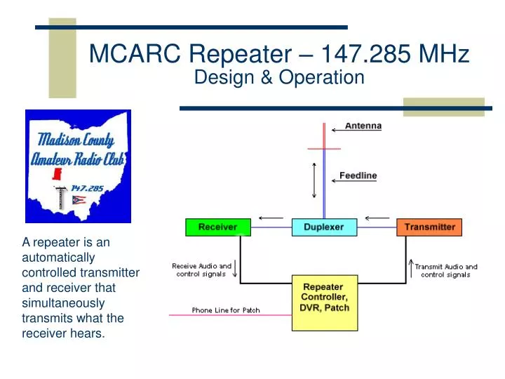
MCARC Repeater – 147.285 MHz Design & Operation. A repeater is an automatically controlled transmitter and receiver that simultaneously transmits what the receiver hears. Components of a Repeater System. Antenna Feedline Duplexer Receiver Transmitter Controller. Basic Repeater Operation.

E N D
MCARC Repeater – 147.285 MHz Design & Operation A repeater is an automatically controlled transmitter and receiver that simultaneously transmits what the receiver hears.
Components of a Repeater System • Antenna • Feedline • Duplexer • Receiver • Transmitter • Controller
Basic Repeater Operation • Offset • To use a repeater a user station must use a different transmit frequency than receive frequency.The difference between receive and transmit frequencies is called the Offset. • Types of Access (Squelch Operation) • Carrier • CTCSS (PL, Tone), DTMF • Digital (DCS)
Squelch Operation • Carrier • Detects white noise. Stronger signals have less noise. Usually in the 4 KHz to 5 KHz range. • CTCSS (PL, Tone, …) • Detects subaudible tone (67Hz to 250 Hz) transmitted by user • Digital (DCS) • Subaudible (134 Baud) continuous digital stream • DTMF (Touch-Tone) • Not often used, but most users have ability to send DTMF
Multiple Receivers & Voting • Extends coverage area of repeater • Good handheld coverage near receive sites. • Voter determines which receiver has best signal • Our system uses signal/noise ratio to determine best signal • All receivers should be matched in level, bandwidth, and linearity. • Our system uses flat, wide bandwidth receivers. • Remote receive sites linked back to the main controller using low power 440 MHz transmitters. • Our system uses flat, wide bandwidth link transmitters.
Multiple Receivers & Voting • Equal audio characteristics ensures seamless voting • System may vote many times per second on a fluctuating signal, but is not detectable listening to the voted output. • Fast squelch and response times necessary to prevent audio “holes” during signal dropouts. • Our system has less than 1 ms response time • Each remote site has a controller to manage timers and squelch control. • Microchip PIC microprocessors are used for controller and CTCSS detection.
Receive Site Control • Squelch Mode: Carrier or CTCSS • “AND” and “OR” type CTCSS mode • Enhanced (loose) carrier squelch • Temporary Modes for Special Conditions • DTMF Control of all functions • Unique CTCSS decoder using DSP technique • Software detection using Goertzel algorithms(n) = x(n) + 2cos(2πω)s(n − 1) − s(n − 2) • Cheap hardware, excellent performance • Overall remote receive site performance indistinguishable from a local receiver – virtually “transparent”.
The ReceiversLondon • Hamtronics R-301 2M VHF Receiver • Hamtronics R-304 UHF Link Receivers • Receivers are synthesized (no crystals needed) • Unsquelched, discriminator audio from the receiver – no de-emphasis • Overall frequency response flat from 40 Hz to 5 KHz • Linear from 0 to 8 KHz deviation
The Voter Hardware The small perf-board circuit is the CW-Beep board that identifies which receiver is voted after each transmission.
Voter and Receivers • The 4 receivers and voter combine to act like a single receiver input into the repeater.
Hamtronics Receive SitesWest Jefferson & Plain City Control Board R-301 VHF Receiver T-304 UHF Link Transmitter • Receiver and Transmitter are synthesized (no crystals needed) • Unsquelched, discriminator audio from the receiver – no de-emphasis • Direct FM modulation of the 2W transmiter – no pre-emphasis or limiting • Overall frequency response flat from 40 Hz to 5 KHz • Linear from 0 to 8 KHz deviation
Hamtronics Receive SitesWest Jefferson & Plain City West Jefferson Site9.5 Miles link distance to London Plain City Site17.7 Miles link distance to London
Motorola / GE Receive SiteMt. Sterling • Receiver and Transmitter use crystal channel elements. • Unsquelched, discriminator audio from the receiver – no de-emphasis • Direct FM modulation of the 10W transmiter – no pre-emphasis or limiting • Overall frequency response flat from 40 Hz to 8 KHz • Linear from 0 to 6 KHz deviation GE Mastr-IIUHF Transmitter Motorola Micor VHF Receiver Motorola Micor30 A Power Supply Mt. Sterling Site – 15.8 Miles link distance to London
Transmitter / Control SiteLondon VoCom 100W Repeater-Duty Amplifier Hamtronics REP-200 Controller(Includes T-301 2 Watt Exciter and LPA2-25 25 Watt Amplifier) Voter and Receivers Assembly Astron RS-35A Power Supply(Not visible – 12V/13AH Battery)
Duplexer • Isolation • 85 dB typical (300,000,000:1 power ratio) • Only 0.4% frequency difference between XMIT & RCV frequency – VERY CLOSE! • Cable leakage, imperfect tuning, and inadequate shielding can easily reduce isolation by 30dB • Insertion Loss • 1.5 dB typical (100 Watts in, 71 Watts out) • Calculation of Required Isolation: • Receiver sensitivity 0.1 uV (-107 dBm), with dynamic range of 75 dB (-32 dBm, 5000μV max receiver input) • Transmitter 100W (+50 dBm) - Duplexer isolation 85 dB =0.3μW (-35dBm, 4000μV) into receiver. Very Expensive - $1200 and up
Dual IsolatorLondon Ferrite Isolators prevent reflected power from damaging the transmitter, and present a constant 50 Ω load to the transmitter regardless of the actual load conditions. Any reflected power is dissipated into the attached dummy loads. The isolator is placed between the transmitter output and the duplexer. It also prevents other transmitters energy that may be at the repeater site from entering our transmitter’s output stage, which could create intermod and other spurious signals. Very expensive - $500 to $1500 typical
Repeater AntennaLondon Very durable antenna – preferred by many repeater operators. Also very expensive, about $700
Future Upgrades • New exciter and 25W amplifier for the main transmitter in London. Crystal controlled, low phase noise for less desense of local receiver. (under construction) • New antenna and feedline in London (awaiting installation) • New link receive antenna for West Jeff link in London (awaiting installation) • Add cooling fan to Astron power supply in London • 82.5 Hz notch filter and CTCSS regeneration at the main transmitter. (enables remote linking capability) • Other suggestions???