
CDC Summary
E N D
Presentation Transcript
CDC Summary Shoji Uno (KEK) July-8, 2009
Baseline Design sBelle Belle
Connection regions 1 Endplate and Outer cylinder Main and Conical (Backward)
Connection regions 2 Main and Conical Backward Forward
Connection regions 3 Conical and Small cell Small cell and Inner cylinder
Wire tension and gravity sag Nanae Taniguchi (KEK)
sag calculation y horizontal cell sense wire : 30μm, 50gw wire length : 2.4 m
wire tension and gravity sag • Current Belle CDC • wire tension is determined to keep the gravity sag of sense and field wire same • 50gw for sense wire and 120gw for field wire • total tension = (50gw x 8400) + (120gw x 8400 x 3) = 3.4 ton • Belle-II • number of sense wire: 8400 →15104 • total tension = (50gw x 15104) + (120gw x 15104 x 3) = 6.2 ton @ same weight • reduce total tension : 120gw → 80gw (base line design) , 6.2 ton → 4.4 ton • however difference of gravity sag is larger
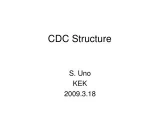
simulation using Garfield HV=2.3kV (sense wire) B = 1.5 T C2H5:50% He:50% ±0.1mm 10
-0.1mm current Belle position resolution ~ 100μm +0.1mm sense wire : 30μm, 50gw (x: distance from sense wire at nominal case)
July 8th, '09 KEK H. Yamaoka Mechanical calculations of the CDC end-plates KEK H. Yamaoka
Definitions for FEM Load conditions Material properties Total: 3725kg Constraints R: Free q: Fixed Z: fixed RotR: Fixed Rotq: Free RotZ: fixed No inner cylinder
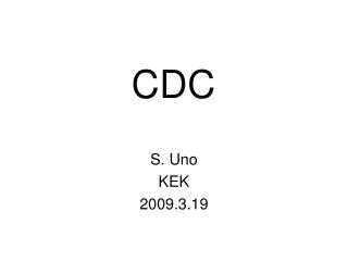
Results - End-plates: 10mm-thick(Al), Outer-cylinder(CFRP): 5mm-thick. Deformation Deformation 2.9mm 2.7mm <5mm : Belle-CDC Stress Stress 31MPa <107Mpa : allowed limit
Buckling strength: Inner cylinder t=0.4mm t=0.8mm Material: CFRP Dia. 340mm Length: 1000mm E:110GPa n: 0.3 Wire tension : 371kg Safety Factor : 6
Readout board space Test board 16ch 48ch(~300boards in total) 17.5cm Should be fit in volume 20cm
CDC readout system status MT 2009 July 7
Test boardfor test(prototype readout card will be designed based on this.) Small tube chamber (tungsten wire) Fe55 5.9 keV X-ray Gas(Ar90%+CH410%), P10 Gas 1.65kV This AmpShaper was developed for other application. Modification will be done by Dr. Taniguchi. RocketIO will be tested by Dr. Igarashi Firmware design will be done by Dr.Uchida FPGA-TDC has been used for J-PARC. Ampshaper 16ch AD9212x2 RocketIO RMS=0.47ns TDC&L1 buf PCB was designed by Mr.Saito and Mr. Ikeno
FPGA Block diagram Trigger FADC I/F Ring buffer 5usec 500nsec window Readout FIFO Q(sum) & Data formatter SiTCP Or RocketIO I/F ADC TDC ASD Slow control DAC, ADC, Ring buffer etc
Pre-AMP test • Nanae Taniguchi (KEK)
Hybrid (NEW+) pre-Amplifier • Rise time is limited by chamber signal → not need to be so fast → lower electric power • The modified PZC cause noise • Found overshoot
make uniform each pulse height set up • small tube chamber • p10 gas (Ar 90% + CH4 10%) • Fe55 5.9 keV X ray (~3xMIP) • HV = 1.575 kV (below saturation point)
Belle AMP Hybrid (NEW+) signal shape make uniform each pulse height with attenuator 1dB 13dB 3dB 12dB
Noise level = Resolution = definition • Fit to Fe55 data with Double Gaussian • Fit to pedestal data with Single Gaussian Fe55 pedestal (random TRG)
Hybrid (NEW+) comparison • 3rd and 4th Hybrid AMP have lower noise • Noise level is enough low • resolution is worse in actual situation
0.1μF stop 1kΩ 51Ω start set up • Timing resolution measurement with pulse generator • TDC • 500ns range • 0.125ns/ch
Resolution • Fit to data with Double Gaussian • Resolution is calculated as weighted sigma • TDC • range 500ns • 0.125ns /ch TDC distribution
Hybrid (NEW+) comparison • 4th Hybrid AMP is comparable with (better than) Belle AMP
Summary of ADC/TDC measurement • 4th Hybrid AMP is usable for base design • We discuss about parameters for prototype of ASIC AMP with T-Taniguchi-san (electronics group) • We will have meeting again before making ASIC pre-AMP • another plan of TDC measurement using laser @ TUAT • signal from chamber • master student is working for the test • Finally, We must do beam test with ASIC AMP • MIP signal and He/C2H6 gas
Schedule(short term) modification Preparation for beamtest Design and feedback submission End of Aug. End of Sept. Nov. Firmware w/o rocket IO prototyping Uchida Amp shaper Taniguchi, Shimazaki Test with rocket IO Nakao, Igarashi PCB design Saito, Ikeno
Introduction ~2400 CDC ~R1090 End-plate Mechanical calculations of CDC end-plates was carried out. Load: Wire tension ~4000kg in total. Material: Outer cylinder CFRP End plates Aluminum, CFRP Assumption: All wire tension is supported by the outer cylinder. Deformation(< 5mm), Stress? Buckling strength?
Wire configuration Given by Taniguchi-san
r Wire tension and gravity sag • small gravity sag, large total tension • distance between sense wire and field wire has z-dependence • asymmetric electric field • asymmetric X-t curve • same distance from sense wire(x), different drift time • affect the position resolution gravity sag field sense field horizontal cell
move sense wire position by amount of +/- 0.1mm put an electron along x-axis calculate the distance from sense wire and drift time obtain X-t curve calculate δx δx is difference of x at same timing nominal δx
-1.0mm -0.5mm -0.1mm +0.1mm +0.5mm +1.0mm current Belle position resolution ~ 100μm sense wire : 30μm, 50gw (x: distance from sense wire at nominal case)
Calculation of deformation and etc Deformation of Aluminum endplate Thickness of endplate 10mm Tension of field wire 120g 80g Gravitational sag, Sense : 190mm(50g), Field:300mm(80g) Unequal sag Nane-san’s talk Total tension ~4ton Deformation Yamaoka-san’s talk Stress calculation Thickness of outer cylinderCFRP:mm Transition structure between endplate and outer cylinder Bucking calculation for inner cylinder Larger tension for many wires ( ~400kg) Yamaoka-san’s talk
Weight Endplate Al, Thickness : 10mm 110kgx2 = 220kg Outer Cylinder CRRP, Thickness : 5mm 210kg Electronics Board G10, 48ch/board 0.3kgx315 = 95kg
Wire configuration So far, 8(A),6(U),6(A),6(V),6(A),6(U),6(A),6(V),8(A), 58 layers in total But, Readout board 64ch/board 16x4 No good assignment 48ch/board 16X3 8(A) 2(A)+6(A) inner most super layer 2(A) special treatment 160x2=320 : 48x7=336 8(A) 6(A) outer most super layer 56 layers in total Good assignment Other good idea is highly welcome.
Calculations of buckling strength Ref: E.H.Baker, et. al. 'STRUCTURAL ANALYSIS OF SHELLS' The buckling strength of the outer/inner cylinder is calculated.
Buckling strength: Outer cylinder If t=1.0mm If t=5.0mm Assumptions Material: CFRP Dia. 2190mm Length: 2328mm E:110GPa n: 0.3 Wire tension : 3725kg
Calculation results in various parameters Allowable stress(Japanese: Koukozo sekkei kijun) This criterion was used for the mechanical design of the Belle.
http://wiki.kek.jp/display/~yamaokah/CDC Conclusion Made by Kohriki-san Configuration - If deformation has to keep less than 5mm, thickness of end-plates should be thicker than 7mm(Al). Calculation at the practical configuration will be necessary. - To know the mechanical properties of CFRP is important, We have contacted to a CFRP fabricator. END
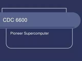
張力分布(リスト) 層 R(mm) Z+(mm) Z-(mm) 数 角度 41 A 814.0 1518.5 -718.5 320 0.0 42 A 832.0 1521.6 -721.6 320 0.0 43 A 850.0 1524.7 -724.7 320 0.0 44 A 868.0 1527.8 -727.8 320 0.0 45 V 886.0 1530.9 -730.9 352 -56.0 46 V 904.0 1534.0 -734.0 352 -56.9 47 V 922.0 1537.2 -737.2 352 -57.9 48 V 940.0 1540.3 -740.3 352 -58.9 49 V 958.0 1543.4 -743.4 352 -59.9 50 V 976.0 1546.5 -746.5 352 -60.8 51 A 994.0 1549.6 -749.6 384 0.0 52 A 1012.0 1552.7 -752.7 384 0.0 53 A 1030.0 1555.8 -755.8 384 0.0 54 A 1048.0 1558.9 -758.9 384 0.0 55 A 1066.0 1562.0 -762.0 384 0.0 56 A 1084.0 1565.2 -765.2 384 0.0 57 A 1102.0 1568.3 -768.3 384 0.0 58 A 1120.0 1571.4 -771.4 384 0.0 層 R(mm) Z+(mm) Z-(mm) 数 角度 1 A 172.0 602.6 -337.9 160 0.0 2 A 182.0 635.3 -355.2 160 0.0 3 A 192.0 668.0 -372.6 160 0.0 4 A 202.0 700.7 -389.9 160 0.0 5 A 212.0 733.4 -407.2 160 0.0 6 A 222.0 766.1 -424.5 160 0.0 7 A 232.0 798.8 -441.8 160 0.0 8 A 242.0 831.5 -459.2 160 0.0 9 U 266.0 910.0 -500.7 160 37.0 10 U 282.0 962.4 -528.4 160 37.1 11 U 298.0 1014.7 -556.2 160 37.3 12 U 314.0 1067.0 -583.9 160 37.4 13 U 330.0 1119.4 -611.6 160 37.4 14 U 346.0 1171.7 -639.3 160 37.5 15 A 368.0 1441.4 -641.4 192 0.0 16 A 384.0 1444.1 -644.1 192 0.0 17 A 400.0 1446.9 -646.9 192 0.0 18 A 416.0 1449.7 -649.7 192 0.0 19 A 432.0 1452.4 -652.4 192 0.0 20 A 448.0 1455.2 -655.2 192 0.0 21 V 464.0 1458.0 -658.0 224 -36.9 22 V 480.0 1460.7 -660.7 224 -38.1 23 V 496.0 1463.5 -663.5 224 -39.3 24 V 512.0 1466.3 -666.3 224 -40.4 25 V 528.0 1469.0 -669.0 224 -41.6 26 V 544.0 1471.8 -671.8 224 -42.7 27 A 562.0 1474.9 -674.9 256 0.0 28 A 580.0 1478.0 -678.0 256 0.0 29 A 598.0 1481.1 -681.1 256 0.0 30 A 616.0 1484.3 -684.3 256 0.0 31 A 634.0 1487.4 -687.4 256 0.0 32 A 652.0 1490.5 -690.5 256 0.0 33 U 670.0 1493.6 -693.6 288 46.8 34 U 688.0 1496.7 -696.7 288 47.9 35 U 706.0 1499.8 -699.8 288 49.0 36 U 724.0 1502.9 -702.9 288 50.1 37 U 742.0 1506.0 -706.0 288 51.2 38 U 760.0 1509.1 -709.1 288 52.3 39 A 778.0 1512.3 -712.3 320 0.0 40 A 796.0 1515.4 -715.4 320 0.0 R+(X+) 内筒なし Z+ Z+
Prototype CDCreadout card (FY2009) # of channels(Total:~15000) 48~64ch/board Amp shaper Shaping time:~100nsec Gain:~1V/1pC(TBD) Dynamic range:2pC(TBD) TDC FPGA TDC Timing resolution:1nsec ADC Resolution:10bit Sampling rate:~32MHz L1 buffer Depth:5usec max Test board was developed to determine above params using test chamber.
Specification of Test board(detail) Analog(Amp-shaper for DB-decay exp) Peaking time:~50nsec OK Pulse width:~200nsec OK Gain : 8V/pC 1~2V/pC Dynamic range : 2V max OK Noise : ~2500 e @ 40pF OK Function ADC 10bit 32MHz TDC 1nsec L1 buffer : 5usec max Two modes for data format Waveform data readout mode Compression mode Timing and Q BLR modification has been done These values will be confirmed by beam test
Amp shaper modification We started development of Amp-shaper for BELLEII CDC. Present Amp shaper Analog buffer BLR Amp shaper CMOS digital Bias circuit