Download
1 / 35
430 likes | 837 Views
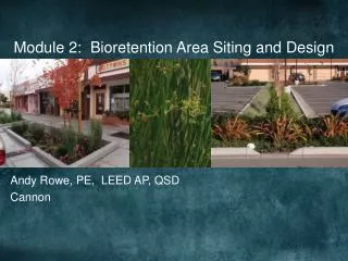
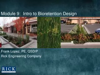
Module 5: Bioretention Design Specs/Details. Melanie Mills, MLA Central Coast LIDI. Specifications & Standard Details. Standard Details. Design Specifications. Design Guidance Review. Expert Panel Review. Design Specifications. Facility Design and Dimensions

E N D
Module 5: Bioretention Design Specs/Details Melanie Mills, MLA Central Coast LIDI
Specifications & Standard Details Standard Details Design Specifications
Design Specifications • Facility Design and Dimensions • width, depth, slope, ponding • Hard Infrastructure • inlets, check dams, overflow structures • Facility Media • soil, aggregate base, mulch • Landscape • plant selection, irrigation
Standard Details • Facility Type • planter • sloped sided • Elements related to facility • walls • curb inlets • overflows • check dams
Facility Design & Dimensions • Bottom width – provide 2’ wide minimum flat bottom for facilities with side slopes and longitudinal slope • Allowable standing water – 72 hours. • Allowable ponding time is typically associated with mosquito vector control, and varies by location. Confirm with local vector control agency to confirm appropriate drawdown time for facility. • Energy dissipation – provide an aggregate or concrete splash pad at inlet per LIDI details. • For aggregate: 6” depth, 3" – 6" rounded, washed cobble • For sloped sided facilities, extend a cobble flow path from pad 1’ into bioretention area bottom.
Side Slope Grades • 3:1 max • needs shoulder • 4:1 recommended
Facility Elevations photo: bluegreenbldg.org Overflow elevation Curb gutter inlet elevation Top of curb Adjacent surface Finished grade in facility
Bioretention w/ Underdrain Planter • Class 2 permeable • No filter fabric • No filter layer • Underdrain • PVC SDR 35 • holes downward • cleanout
Bioretention w/ Underdrain Side Slope • Underdrain design considerations • design w/ future modification • adjustable orifice • open/close drain
Design Specifications Hard Infrastructure
Curb Cut Inlets for Planters Inlet design has evolved
Curb Cut Inlets for Sloped Sides City of Portland, Environmental Services
Energy Dissipation Cobble • Use it for energy dissipation • at inlets • sloped sides/extend down to facility bottom • Avoid decorative use • difficult to maintain • weeds can establish in sediment/cobble
Inlet w/ Grate SW 12th Ave., Portland, Kevin Perry
Gravel Check Dam City of Portland, Environmental Services Mild longitudinal slope
Concrete Check Dam Pittsburgh Courthouse, photo: bluegreenbldg.org
Concrete Check Dams • Work w/ steep longitudinal slope • Series of bathtubs photo: Tracy Tackett, SPU
Check Dams • Other rigid materials • steel • clear plexiglass • concrete w/ wood
Overflow Structure w/ Beehive Grate photo: SvR Design Required for systems without overflow bypass Overflow raised to allow ponding Connects to downstream structure or stormdrain
Overflow Structure w/ Collar photo: Kevin Perry
Location of Overflow TOP 10 Not adjacent to inlet Raised to allow for design ponding
Design Specifications Facility Media Landscape
Aggregate • Optional use – per project requirements • Cal Trans Class 2 Permeable • No filter fabric • potential for clogging • inhibits infiltration • Aggregate filter layer not needed for Class 2 • If Class 2 not available, substitute Class 3 • provide 3” depth filter layer for Class 3
Future Standard Details • Layout details for bioretention • street edge with parking • curb extensions • bioretention with pedestrian crossing • parking lot layouts