Gear Bearing Technology
Gear Bearing Technology. December 9, 2003. Group 14: Pamela Carabetta Marisa Jenkins Sarah Kovach-Orr Anuja Mahashabde Qi Yan. Advisors: Mr. John Vranish Prof. Dinos Mavroidis Dr. Mircea Badescu Ms. Kathryn De Laurentis Mr. Brian Weinberg. Project Description.

Gear Bearing Technology
E N D
Presentation Transcript
Gear Bearing Technology December 9, 2003 Group 14: Pamela Carabetta Marisa Jenkins Sarah Kovach-Orr Anuja Mahashabde Qi Yan Advisors: Mr. John Vranish Prof. Dinos Mavroidis Dr. Mircea Badescu Ms. Kathryn De Laurentis Mr. Brian Weinberg
Project Description • Need for improvement on existing planetary gear transmissions • John Vranish of NASA invented the “gear bearing” • Apply gear bearings to space exploration technology • Use gear bearings in a robotic wrist – possibly mount on explorer type robot
Mission Statement • A robotic wrist that moves with greater precision and produces greater torque than those currently available through the use of gear bearings • Major Goals: • -Finalize the design of this robotic wrist along with its expected performance values by December 2003 • -Create a working model by May 2004.
Significance • Robotic wrist should have improved precision, smoothness, and lift capability to weight ratio. • Potential applications outside of NASA: General robotics, prosthetics • 2 degrees of freedom
Background: Planetary Gears Outer Ring Sun • Transmit higher torque • Low-backlash • Distributed load (longer life) • Works well with high-speed inputs (ideal for motors) • Limitations: small gear ratio, size, weight, cost Planet
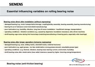
Gear Bearings • Advantages over planetary gears: • Phase-shifted for greater speed reduction • Lighter • Smaller • Cheaper • Stronger • Smoother (ME Magazine, 2002)
Gear Bearing Kinematics • Gear Bearing = 180 = = • Planetary Gear -Stationary Carrier/Rotating Ring: = 2 = -Stationary Ring/Rotating Carrier: = 3 =
Existing Robotic Arm Rover Multidimensional Gear Bearing Robotic Arm Robotic Wrist and Hand Predicted Quality of End Product 1.)Referring to lab capabilities 2.)Referring to group’s capabilities 3.)Referring to time frame 1 4 4 4 3 5 3 2 2 4 3 4 5 5 3 Meaningfulness 1.)To group members 2.)To NASA 3 1 0 2 4 5 3 3 5 4 Risk of Failure 3 2 1 3 2 Challenge to Group 2 4 5 4 5 Market Need 1.)Application to NASA 2.)Application to Robotics Industry 1 1 4 2 5 5 3 3 4 4 Cost 4 1 5 4 4 Total 24 27 37 34 39 Ideas: Selection Matrix
Concept Evolution Original Ideas: Robot Arm, Rover, Improve Existing Arm, 2D Gear Bearing, Robot Hand/Wrist Arm on Rover, 2D Gear Bearing, Robot Wrist New Direction: 2 Degree of Freedom Robot Wrist • Create robotic wrist with two degrees of freedom • Greater precision • Lift capability vs. weight
Need Statements No. Need Imp. 1 the gear bearing reduces vibration in the arm 5 2 the gear bearing greater speed reduction 4 3 the gear bearing is lightweight 4 4 the gear bearing is compact 4 5 the gear bearing is easy to install 1 6 the wrist durable 5 7 the wrist is safe to user while in use and when not in use 5 8 the gear bearing high precision to pick up object 5 9 the wrist 2 degree of freedom 4 10 the wrist less motor torque required 3 11 the wrist perform more like human wrist 5
Metrics Metric No. Need Nos. Metric Imp. Units 1 1 Damping coefficient range 5 N-s/m 2 2 Total torque 5 N-m 3 3 Total mass 4 Kg 4 4,10 Sizes 4 in. 5 4,10 Costs 3 Dollars 6 5 Time to assemble 3 S 7 6 Number of cycles to failure 5 Cycle 8 7 Bending strength 5 KN 9 8,11 Accuracy 5 Percentage 10 9 Area of movements 5 m2
Need – Metrics Table
Design Specifications • Gear Bearing: input ring – 57 teeth, sun – 27 teeth, driver planets – 15 teeth output ring – 58 teeth driven planets – 15 teeth 9 in-lb torque ability • Wrist: Approximate Dimensions: 6in X 5in X 6in Lift 3 lbs Approximate Weight 1lb (without motor and gear bearings)
Exploded View Gear Bearings
Safety Features • Moving parts (motors, gear bearings) are enclosed within the structure • Gear bearings allow for smaller motors • Encoders on the motors
Parts and Cost • Rapid Prototype: epoxy resin ~$500 (overestimate) • Motor and Optical Encoder: $189 from Micromo • Screws: $2-10 box from the Home Depot • Metals of choice: stainless steel, titanium, aluminum
Discussion and Conclusion • Gear bearings are superior to planetary gears • Use gear bearings to create a 2 degree of freedom robot wrist • Create working model using rapid prototyping • Potential applications outside of NASA
Acknowledgements Mr. John Vranish & NASA Goddard Space Flight Center Advisors: Ms. Kathryn De Laurentis, Dr. Mircea Badescu, Prof. Dinos Mavroidis, & Mr. Brian Weinberg ME Magazine, 2002