Download
1 / 10
100 likes | 254 Views
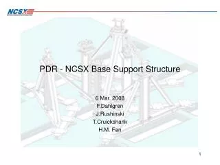
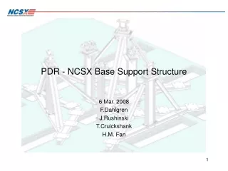
A View of NCSX Structural System and Load Path for the Base Support Structure. TF Support Frame. Upper and lower TF support frames are symmetry to the mid-plane. The inner frame and the outer frame are connected by T-shape beams to resist the TF vertical EM load.

E N D
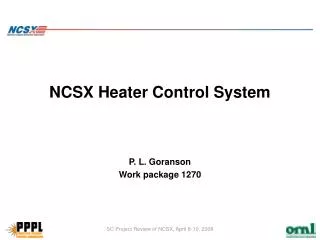
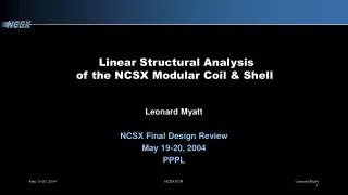
A View of NCSX Structural System and Load Path for the Base Support Structure
TF Support Frame • Upper and lower TF support frames are symmetry to the mid-plane. • The inner frame and the outer frame are connected by T-shape beams to resist the TF vertical EM load. • The frames are formed by casting pieces and bolted together to form continuous elements in the toroidal direction. • The frames are bolted to the “feet” of the modular coil shell structure. • The upper frame and the lower frame do not connected by any structural members. Loads from the upper frame will go through the shell structure to the base support. • The frames also support the PF coils eccentrically.
Bolt joints between casting pieces Inner Support Frame • The bending and torsion rigidity of the ring-shape frames are best provided by the continuity of the cross section along the toroidal direction when the castings are securely tightened • Bolt joints between casting pieces are weak for bending and torsion
Outer Support Frame • The frame provide better stiffness in the radial direction, but weaker in the toroidal direction. • Only the upper plate is continuous in the toroidal direction.
Center Stack OH Coils • The center stack for the OH assembly is preloaded and mounted on the top inner frame
Loads and Load Paths • All loads will be either balanced each other or carried down to the base support structure. • The distributions of the loads to the adjacent components depend on the type of the loads and the rigidity of the interacting structural components • Dead weight - As the shell structure is more rigid than the TF support frame, most of the weight will be carried through the shell to the base support structure • EM loads: Because of the symmetry nature of loads, some loads will be balanced each other, some will be transferred through the shell, and some at the lower TF support frames will be reached the base support directly. • Thermal load: Uniform cooldown to 80°K will cause minimum stress if structure is allow to move freely in the radial direction in the same plane. Therefore, if sliding point is designed, it shall be verify that the joint will be able to slide during cooldown. • Seismic load: Horizontal loads will be restrained by the support posts that do not slide in the force direction. .The vertical loads will be similar to the dead load.
Bolt Joint Design Considerations • The NCSX structure transfers forces from one component to the other component by bolted joints. • Bolt joints are best located at where the bending moment is small, so the tension in the element will not reduce the bolt preload. • Because of the EM loads are not static, It is recommended (or required) to design the bolt joint as a friction joint, not the shear joint. • The bolt preload depends on the bolt capacity. The determination of the preload magnitude should also consider the preload change due to thermal expansion of different materials caused by temperature variation and the creep of the insulation material at the joint if any. • The bolt joint shall be locked in position because of transit in the load nature
Shear Force in the Shell Due to Bending • As the TF support frame do not provide much continuous areas in the toroidal direction, The bending rigidity of the system will mostly depend on the shell. • For a beam with continuous cross section, the shear stress due to vertical shear force in the cross section is: • Szx = VQ/bI Where V = shear force Q = area moment b = Thickness of total shell walls I = moment of inertia of the cross section • As Q is maximum in the mid-plane, without the port opening in the shell, the maximum vertical shear stress will be near the mid-plane. • There are no bolts available at the shell inboard joint. The compression at the inboard will depend on the bolt preloads at the upper and lower flanges. • In shell cross section, bolts on the top and bottom flanges take most of the bending stress. • The shear force V and the bending moment are primarily determined by the magnitude of loadings and the spacing between the supports
60 30 30 (5/6)L 2.5 0.5 -0.5 -2.5 Shear Diagram 60 30 30 (1/2)L 1.5 1.5 -1.5 -1.5 Shear Diagram Design of the Base Support - Simple Beam Analogy • The center of gravity of the NCSX module is located approximately one third of the distance between inner post and outer post, Therefore, for the dead weight, the vertical load in the outer post is about twice as big as the load of the inner post. • The equal spacing base post design provide not only small bending stress but also small shear force in the cross section
Summary • The modular coil shell structure become the primary structure to transfer loads to the base support structure because the upper TF support frame and the lower TF support frame do not connected by any structural members • The shell structure is basically a circular tube in shape. In additional to the stress in the shell, it strength and rigidity depends on the capability of the bolt joints. • Bolt joints are best located at where the bending moment is small, so the tension in the element will not reduce the bolt preload. • The equal-spacing base post design provide not only small bending stress but also small shear force in the cross section • The base support locations and moving constraints, such as sliding joint will affect the structural responses of the upper structure. • Because of the EM loads are not static, It is recommended (or required) to design the bolt joint as a friction joint, not the shear joint. • It is suggested that the center stack for the OH assembly is mounted at the bottom inner frame to lead the loads directly to the base support