Download
1 / 9
90 likes | 216 Views
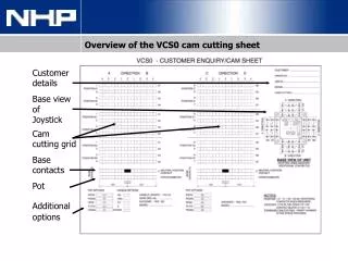
Customer details. Base view of Joystick. Cam cutting grid. Base contacts. Pot. Additional options. Overview of the VCS0 cam cutting sheet. Terms used in this training. D. Base view of joystick. 7. 07. D. 08. 8. Cam-cutting grid.

E N D
Customer details Base view of Joystick Cam cutting grid Base contacts Pot Additionaloptions Overview of the VCS0 cam cutting sheet
Terms used in this training D Base view of joystick 7 07 D 08 8 Cam-cutting grid
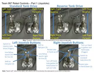
Direction: The “direction” refers to the movement that the joystick is operated - A, B, C & D. Direction is labeled on the contact diagram for the base view of a joystick as well as the cam cutting grid (as below). Position: The “position" refers to the double contact block location. A maximum of 3 doublecontact blocks can be fitted to each side of the joystick. The first double contact block on each side is not marked on the base view. The contact block position is also labeled on the cam cutting grid. D Base view of joystick Gates: Varying gate options can be fitted to a joystick to limit the direction of travel. For example, if a cross gate was fitted to a 4 direction controller, the handle of the joystick can only travel in the direction of the slots in the gate. A joystick without a cross gate allows the handle to move freely across axis without returning to the neutral position. 7 07 D 08 8 Cam-cutting grid
Steps: “Steps” are increments that the joystick can move when operating from the neutral position in a direction. The maximum number of steps for a VCS0 controller is 6 in each direction. The number of steps in one direction doesn’t need to be the same as the opposing direction. This can be achieved by limiting the travel of the handle during manufacture. Stepless: If a potentiometer is included in a joysticks construction a “stepless” motion is commonly used. Stepless means there is no increments within the motions. Base contacts: The “base contacts” are designated contacts to the neutral position. Every VCS0 joystick is supplied standard with 1 base contact for each motion. The base contact is closed in the neutral position. Motion: A one motion joystick is a joystick with one axis, being either up-down or left-right. A two motion joystick has both axis.
When the joystick is moved into a position, contacts associated with that motion either make or break depending on the cam cutting configuration specified by the customer. Identifying contacts on the base view A Direction 2 - 02 and 3 - 03 B Direction 1 - 01 and 4 - 04 C Direction 5 - 05 and 8 - 08 D Direction 6 - 06 and 7 - 07
How the base-view translates to the cam-cutting grid Position A Position B Position C Position D Position A1 Position B1 Position C1 Position D1 PositionB2 PositionD2 Position A2 Position C2
Direction A Shading for A to be within this area Shading for B to be within this area Shading for C to be within this area Shading for D to be within this area Direction B Direction C Direction D
1st Contacts in ‘B’ direction 1 - 01 Using ‘B’ direction as an example 2nd Contacts in ‘B’ direction 4 - 04 3rd Contacts in ‘B’ direction 1 - 01 4th Contacts in ‘B’ direction 4 - 04 5th Contacts in ‘B’ direction 1 - 01 6th Contacts in ‘B’ direction 4 - 04 The auxiliary contacts for ‘B’ direction are as follows. The contacts for the ‘A’ , ‘C’ & ‘D’ direction will be similar.
Example 1 shows our 1st contact for direction B and direction A making in the 1st step only. How a customer translates to the cam-cutting grid Example 2 shows our 2nd contact for direction B making from the neutral/0 to the 1st step. 1st Example 3 shows the 2nd contact for direction A making from the neutral/0 to step 1 and also on the 3rd step of direction B. 2nd Example 4 shows our 3rd contact for direction B and A making from the 1st step to the 4th step (common cam cutting for potentiometers). 3rd 4th Example 5 shows our 4th contact for direction B and A making in the neutral only. The same principals apply for directions C & D Neutral position