Download
1 / 18
360 likes | 1.33k Views
Lam Enhanced Gas Box. Jack Long. 4/27/2004. Topic. GAS BOX OVERVIE W GAS DELIVERY COMPONENT S GAS DELIVERY AND FUNCTIO N GAS BOX ELECTRONIC S GAS BOX CONTRO L GAS BOX COMPOENTS REPLACE S. Gas bo x View. CUSTOMER JUMPER J37,J11. Exhaust port. LED STATUS. EMO button.

E N D
Lam Enhanced Gas Box Jack Long 4/27/2004
Topic • GAS BOX OVERVIEW • GAS DELIVERY COMPONENTS • GAS DELIVERY AND FUNCTION • GAS BOX ELECTRONICS • GAS BOX CONTROL • GAS BOX COMPOENTS REPLACES
Gas box View CUSTOMER JUMPER J37,J11 Exhaust port LED STATUS EMO button Interlock signal cable J3 POWER cable J1 CDA regulator N2 Purge regulator Solenoid banks LEDS Lon work cable J2
GAS BOX ENCLOSURE COMPONENTS Mass Flow Controllers Primary Gas Delivery Valves V10-V120 Pressure Transducers Regulators Chamber Delivery Vacuum Switch PS3 Secondary Gas Delivery Valves V12-V122 Gas Purge valves V11-V121 Hand valves Gas Manifold Precharge Valve V4 Gas inlets(12) Filters Gas Manifold Purge Valve V3 N2 Primary Valve V1 Vacuum Primary Valve V2 N2 Purge Supply Switch PS9 N2 Pressure Regulator N2 Pressure Gage N2 Ballast valve V8 Chamber N2 Purge Valve V9 Precharge Manifold Vacuum Switch PS2 Chamber Gas Delivery Valve V5 Pneumatic Solenoid Banks Process Gas to Chamber N2 Inlet
Special gas flow chart (1) Gas Inlet HAND VALVE REG Chamber Gas Inlet HV11 PT10 V10 MFC1 V12 V5 Chamber
Gas box purge flow chart (2) Purge N2 Purge V9 Chamber PR8 V8 V1 V11 MFC1 V12 V3
Gas box pump flow chart(3) Pump Pump V2 V11 MFC1 V12 V4
Gas Box Electronics • Gas Box Electronics Enclosure • Connections to PM • DC Power Cable 24Vand –15V • Lon Works cable • Interlock PCB signal cable • Customer Gas Detect / interlock jumper • Gas Box PCBs • I/O Mother / interlock PCB • Node 3 and Node 4 PCB • Gateway PCB Interlock table Diagnostic states LED • Control and interlock status Solenoid bank states LED • 32DOs,24DIs,16AIs,8AOs signals • Digital MFC Control
Gas Box Control Flow Chart Node ¾ PCB SOV AOV PM VME I/O Mother& Interlock PCB UI GATEWAY PCB MFC Interlock signal
GAS BOX COMPONENTS REPLACEMENT • Preparation • Ensure that system is in process idle stat • Close this gas line Manual valve • Performing the chamber and gas box pump/purge ,procedure(202-803234-002,202-803256-002) • Measuring the chamber and gas box leak back rate<1mt and transducer display <-14psi • Procedure • Open the gas panel • Remove and replace the components • Install the new gaskets onto components • complete the procedure • Perform 20 pump-and-purge cycles on the chamber and gas panel • Test the gas box leak back rate<1mt • Slowly open components manual valves. Allow gases to flow for five minutes • Perform gas calibrations on the gas channels that have been serviced • Perform the partial pressures test • Record observations and work performed in the system logbook. • Note For best results, ensure that MFCs have been powered up for at least two hours before performing gas calibrations
Gas Box PCB Mother board Gateway PCB Node 3 Node 4
Gas box Diagnostic Status LEDs • DS6 ON=PSH3,PSH8,IS20,IS21are all True • DS5 ON=IS20 AND IS21 are both True • PS2 Precharge Manifold @VAC (<75 Torr) • PS3 Chamber Delivery @VAC (<400Torr) • PS8 Scrubber Switch (>0.5 H2O) • PS9 N2 Purge supply (>10 psi) • IS20 Customer gas detect • IS21 Customer interlock switch • SOV1 N2 Primary valve • SOV2 VAC Primary • SOV3 Gas manifold purge valve • SOV4 Gas manifold precharge valve • SOV5 Chamber gas delivery valve • SOV7 Chamber gas vent valve • SOV8 Chamber wafer Transfer • Spare • spare
Gas Box Cable POWER CABLE (9 pin) Lon Work Cable (RJ45 ) (8 pin) Interlock signal cable (25 pin) P/N :853-017573-001 P/N : 833-016952-001 P/N:833-017572-001 3 1 6 4 9 7 1.+24VDC 2.+24VDC 3.RTN 4.KEY 5.-15V 6.CHASSIS GND 7.+24VDC 8.RTN 9.RTN
Gas Box Connection Cable • Customer Interlock Jumper • Gas detect • Door interlock Interlock signal cable(25 pin) Lon work cable x2(8 pin) Power cable(9 pin)
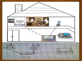
Special gas line from facility Gas Lines
Solenoid Bank LED States SOV AOV Valve Name