Scale and Temperature Compensation in Spatial Analysis: Best Practices for Accurate Measurement
This presentation by Zach Rogers and Philip Wilson delves into the intricacies of scale and temperature compensation in measurement processes. It explores the impact of temperature on materials, emphasizes the importance of Coefficient of Thermal Expansion (CTE), and outlines best practices for managing scale adjustments. Key topics include the role of instrument weather stations, the significance of consistent measurement processes, and the effective use of floating scales. Attendees will gain critical insights to enhance measurement accuracy and reduce uncertainty in spatial analysis.


Scale and Temperature Compensation in Spatial Analysis: Best Practices for Accurate Measurement
E N D
Presentation Transcript
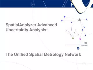
Scale and Temperature Compensation with SpatialAnalyzer Zach Rogers & Philip Wilson (the out of town guys)
Background • Design at 20°C, measure at ? • Materials will grow & shrink w/ temperature CTE = Coefficient of Thermal Expansion • Grand assumption is that our materials are isotropic and CTE is linear • 1-(Tmeas-20°C)*CTE=Scale
Instrument Weather Stations • Most instruments have a weather station Records temperature, pressure, & humidity • Instruments might also contain internal temperature sensors Usually record temperature • These sensors compensate the instrument, not the component being measured Instrument weather station information is always stored with the measurement
How Important is Scale CTE of Aluminum ~0.001”/100”length/degF* Typical measurement uncertainty for 100” measurement = ~0.001” *Actually it’s worse than that, but I like round numbers
Do parts really expand and contract linearly? . • No • All methods of temperature compensation have inherent limitations. Components are not always one homogenous thing (bolted, riveted, welded, clamped, & glued at all different orientations) Do parts really expand and contract linearly with temperature? Sometimes you really do need a temperature controlled facility…
What about scale bars? Scale bars are an option for setting scale when… • They are the same material as the object being measured • They are at the same temperature as the object being measure • They are sufficiently long • There is more than one, or more than one set of measurements on the scale bar Scale bars can make great thermometers
So what to do? • First and most important, don’t change unless you know how you will affect downstream processes! You may have somebody downsteam that is expecting uncompensated data. Why? Who knows, but it happens. • Second, be consistent. Scaling can be done different ways & at different points in the process. Reduce uncertainty – use a consistent process • Third, do not ALWAYS float scale Floating scale is great, but first you need something have something to float it to
So, really… what do I do? Set scale at the instrument levelThis scales all measurements Scale point groups individuallyCopies and Scales selected point groups Scale Nominals or CADNot common, but you can do it
3 Step Best Practice • For the initial measurement, set scale based on part temperature InstrumentProperties & Set Scale Manually InstrumentLocateBestFit & Set Scale Manually • When tying in for subsequent measurements or performing a station move, float scale • If a drift check fails, always evaluate scale
Scaling Individual Groups or Objects Scaling Individual Groups Scaling Objects or CAD
Setting Scale at the Instrument SA will always note instruments which have been scaled in the treebar
When to Set Scale? At the start of the measurementUsing measured temperature or scale bars • All measurements are corrected as you take them • Constructed objects using measured data will use the scale at the time of construction • Instrument location, fits, & co-ordinate systems will all use the defined scale At subsequent tieins, station moves, or after failed drift checksUsing measured temperature, scale bars, or floating scale • Floating scale can correct scale drift At the end of the measurementUsing averaged temperature • When part temperature changes are unavoidable, this may be your best option • Verification, analysis, and construction geometry will all need to be done after scaling is performed
Floating Scale Enable Here A.K.A. “7-DOF Fit” Use When… • Moving Station and refitting to previous measurements • Part reference system has already been established at design conditions by previous measurements Do not use when… • Part Scale has not yet been determined Verify Here
Floating Scale in USMN Scale can also be solved for when using USMN… Enable Here
3 Step Best Practice • For the initial measurement, set scale based on part temperature InstrumentProperties & Set Scale Manually InstrumentLocateBestFit & Set Scale Manually • When tying in for subsequent measurements or performing a station move, float scale • If a drift check fails, always evaluate scale