SpatialAnalyzer Advanced Uncertainty Analysis:
SpatialAnalyzer Advanced Uncertainty Analysis:. The Unified Spatial Metrology Network. Presentation Outline. Background and Motivation Instrument Uncertainty Characterization Discrete Point Cloud Uncertainty Fields Combining CASs – Traditional Approach

SpatialAnalyzer Advanced Uncertainty Analysis:
E N D
Presentation Transcript
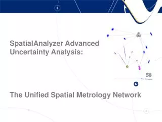
SpatialAnalyzer Advanced Uncertainty Analysis: The Unified Spatial Metrology Network
Presentation Outline • Background and Motivation • Instrument Uncertainty Characterization • Discrete Point Cloud Uncertainty Fields • Combining CASs – Traditional Approach • Unified Spatial Metrology Network (USMN) • Case Studies
Measurement Tools Portable CMMs Theodolites & Total Stations Digital Photogrammetry Laser Trackers Fixed CMMs Laser Scanners
Background Need: General Software Common User Interface Unify Metrology Processes • Many instrument types and models in use. • Each manufacturer has individual, incompatible, software applications. • Users need to apply several devices to a single measurement task. • Operators need to re-train on each software package. ? Combined Results Software A Software B Software C
Motivation • Uncertainty statements must accompany measurements. (NIST TN/1297, ISO Guide, ANSI GUM, NCSL RP-12) • Coordinate measurements used to make important (and expensive) decisions • Multiple systems are often used to perform a single measurement job. • Current industry practice is to make guesses at (or ignore) overall combined uncertainty based on instrument manufacturer specifications. • Needed: • Instrument performance in the “real-world” • Geometric representation of uncertainty • Combination of measurements and uncertainty • Task-Specific Uncertainty (geometrical fits, etc.)
Questions… Questions… Questions… • What is the uncertainty of my instruments in the “real-world”? • What is the effect of uncertainty propagation on the quality of my measurements? • How can I make optimal use of my measurements to minimize uncertainty? • Ok, its nice to know the uncertainty of a point, but I’m fitting a cylinder. What is the uncertainty of my fit? • What about my hidden point bar?
Unified Spatial Metrology NetworkAnswers… Answers… Answers… • Combine measurement systems • Characterize instrument uncertainty • Verify instrument performance • Determine uncertainty fields • Take advantage of the relative uncertainty of the measurement components. • Geometric fitting uncertainty (sphere, line, plane, cylinder, etc)
Coordinate Acquisition System (CAS) Uncertainty Characterization • Measure the performance of the entire system under the conditions of interest. • Include instrument, operator, environment, etc. • Determine uncertainty of compensated instrument output values. • Determine effect of these uncertainties on the measured coordinates.
Measurement Process • Establish a field of unknown fixed points. 56 feet
Measurement Process • Measure the points from the first instrument location.
Measurement Process • Measure the points from the second instrument location.
Measurement Process • Measure the points from the third instrument location.
Measurement Process • Measure the points from the fourth instrument location.
Point Computation: Find Minimize Instrument Transform Computation: Solve for Instrument Transformations Find Minimize
Extract Uncertainty from Residual Errors • Group residuals by component • “Type A” uncertainty evaluation • Result:
Coordinate Acquisition System Outputwith Realistic Uncertainty Statement Uncertainties including all measurable effects: operator, environment, target, mechanical backlash, etc. Coordinate Acquisition System
Combining 2 CASs – Traditional Approach • Match common points by minimizing residuals. • Apply transformation to all points and the instrument.
Chain of CASs - Traditional Best-Fit • Transform tracker to CAD • Transform Arm to Tracker • Transform Scanner to Arm • All transformations based on XYZ coordinate residuals • Usually performed using multiple software packages
Unified Spatial Metrology Network:A Method for CAS Combination • Simultaneous combination of CASs • Relative uncertainty weighting for measurements • Determine uncertainty fields based on CAS combination. • Task-Specific: Apply uncertainty fields to downstream analysis.
Relative Uncertainty Weighting in Point Computation • Different instrument types • Different uncertainty characteristics • Weight measurement components based on relative uncertainty.
Weighting Example U m D W e
USMN Uncertainty Analysis 2 Instruments Before Combination
USMN Uncertainty Field Analysis Network Solution with Actual Measured Values Inject U into all measurements Network Solution with Measured + U Values Composite Coordinate Set + Uncertainty Field
USMN Uncertainty Propagation Fixed Reference 2 Instruments After Combination
USMN Uncertainty Propagation Add a 3rd Instrument to the Measurement Chain
USMN Uncertainty Propagation Fixed Reference Add a 3rd Instrument to the Measurement Chain
USMN Uncertainty Propagation Fixed Reference Close the Measurement Loop to Reduce Uncertainty
Task-Specific Measurement Uncertainty • Given point uncertainties, how is my actual measurement job result affected? • What is the uncertainty of a sphere fit? • Hidden Point Bar? • Go/No Go Decision? How certain are you it’s a GO?
USMN Task-Specific Uncertainty • Given coordinate uncertainty fields…. • What is the uncertainty of the sphere fit in part coordinates?
USMN Task-Specific Uncertainty • What is the uncertainty of the measured cylinder axis and diameter?
Analysis: Hidden Point Bar Uncertainty • Uncertainty Fields Interact • End-Point is extrapolated… • And so is the uncertainty! • Yikes!
Case Studies • Aircraft Carrier Catapult Alignment (CVN-76) • Disney Concert Hall Panel Positioning • Submarine Fabrication (SSN 774) • Nuclear Power: Steam Generator Replacement
Aircraft Carrier Catapult Alignment (CVN-76) • Long narrow structure • 350’ x 6’ trough • 4 laser trackers chained together
Catapult 1,797 Measured Points 300 field samples 15 minute run time P-4 1.8 gigahertz
Disney Concert Hall (LA) 285 measured points 300 field points 11 minute run time P-4 1.8 gigahertz
296 points 1.6 sec. for single solution 300 field points 28 minutes run time P-4 1.3 gigahertz
Uncertainty Chain 106 points 300 field points 9 minute run time P-4 1.8 gigahertz