Sensor design and mass test system development
280 likes | 421 Views
Sensor design and mass test system development. Y. Kwon (Yonsei Univ.). F irst real scale prototype chip from CERN. Our involvement. Participation in chip design Preparation of mass test system. Chip design. Chip design opportunities. Interesting approach based on CIS technology

Sensor design and mass test system development
E N D
Presentation Transcript
Sensor design and mass test system development Y. Kwon (Yonsei Univ.)
Our involvement • Participation in chip design • Preparation of mass test system
Chip design opportunities • Interesting approach based on CIS technology • Joint efforts with Prof. M. K. Song @ Dongguk Univ. • 2013-2014 : two master degree course students • 2014-2015 : two doctorate degree course students • Student 1 : Daehyeok Kim • Continuation from 2013 • Involvement in front end development • Student 2 : Sungjoo Lee • New involvement • Past experiences in analog/digital circuits.
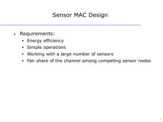
Issue for the mass test system • 50k delicate pixel sensors • Test configuration • Probe card • Chuck • Test definition : Laser, readout • Automation (machine vision + robot, commercial solution available) • To pick chips from tray, • load them on chuck, • test them according to the test configuration, • and return to the holder. Minimum system to do custom chip test.
PAD layout Total 103 pads to make contact
Task 1, probe card CPU FPGA ETHERNET
Specification 0. Dual pins for each pad Pin A for external connection (power/ground/IO), Pin B to check pin contact with the pad 1. 103 x 2 = 206 pins. 2. 14 + 3 relays as switches when we decouple pin A and pin B 3. 8 LEDs to check probe card position by eye. 4. Contact status check at every 10 ms. 5. Contact status report by ethernet.
PAD size We want dual pin contact for each pad.
Probe needlelayout Invisible Chip
Programming option • Computer + ethernet • Slow, but flexible • On-board CPU • In-between • FPGA • Fast, but limited
Pin A Pin B Input
Algorithm to check contact Disconnect power/input using relay. Send 1.8(V) logicpulse to each digital input pad via pin A and read pin B. If no pair read back, raise chuck via . If any pair reads back, 3. Start careful adjustment ’. 4. Send 1.8(V) sequential logic pulse to other digital input pad via pin A and read pin B. Raise ’ up until all input pad pairs read back. Send 1.8(V) sequential logic pulse to digital input pads via pin A and read pin B. (We will skip step 6 if we worry damage by electrical shock).
7. Raise ’ up until all input pad pairs read back. 8. FPGA pull down for power pin B, FPGA pull up for ground pin B. 9. Disconnect FPGA output for pin A. 10. Connect power. 11. Check FPGA pin status 12. Raise ’ up until all pin B status is OK. 13. Disconnect pin B for analog input. Use LED to display current status properly. FPGA flexibility enables variation of algorithm.
Transparent chuck? Suction control One hole Would sensor be flat on the chuck?
Problem Sensor Chuck Vacuum hole Chuck
Solution More small holes, air-tight chuck
Chucks in preparation We are evaluating the optimal configuration.
Test definition? • Basic elements are ready. • Open chuck in page 24 • Laser (1000-1100 nm)? • X-Y stage with optical mask • Requires further communication with CERN
Status • Optimization in progress with the delivery of proto type sensor. • R&D in coordination with CERN --- We exchange experiences.