Download
1 / 15
170 likes | 318 Views
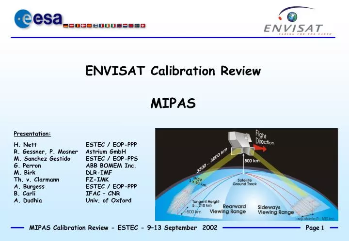
ENVISAT Calibration Review MIPAS. Presentation: H. Nett ESTEC / EOP-PPP R. Gessner, P. Mosner Astrium GmbH M. Sanchez Gestido ESTEC / EOP-PPS G. Perron ABB BOMEM Inc. M. Birk DLR-IMF Th. v. Clarmann FZ-IMK A. Burgess ESTEC / EOP-PPP B. Carli IFAC – CNR

E N D
ENVISAT Calibration Review MIPAS Presentation: H. Nett ESTEC / EOP-PPP R. Gessner, P. Mosner Astrium GmbH M. Sanchez Gestido ESTEC / EOP-PPS G. Perron ABB BOMEM Inc. M. Birk DLR-IMF Th. v. Clarmann FZ-IMK A. Burgess ESTEC / EOP-PPP B. Carli IFAC – CNR A. Dudhia Univ. of Oxford
3. LOS Mispointing Analysis & FOV Check
LOS mispointing analysis Orbits # 2622 & 2623 (31 Aug) Scenario: • 3…7 passages per IR star • determination of star arrival time through cross-correlation with a reference signal • co-addition of individual passages to enhance SNR Model: Del = A0, pitch+A1, pitch * cos(worb*t - Fpitch) Daz = A0, roll +A1, roll * cos(worb*t - Froll) [worb = 2*p/Torb (Torb = 6036 s)]
LOS mispointing characterisation Cross-correlation analysis: • sampling at 10 ms ( ~ 0.6 mdeg) • ‘peak find’ after co-addition • parabolic fit • search radius: 750 ms (+/- 45 mdeg pitch) • weighting: D1 = 1, D2 = 0.1 In example (RAFGL 4292): Tanx = 1612 s Dt = -415 ms da = 24.9 mdeg total # stars: 62 (2 orbits)
LOS analysis: results Comparison: LOS calibration in orbits 1522 & 1523 (24-AUG-2002) A0, pitch = 17.9 mdeg A0,roll = 0.6 mdeg A1,pitch = 10.7 mdeg A1,roll = 1.7 mdeg vFpitch = 72.1 deg Froll = -103 deg
Recent corrections applied: • Mission planning:- correction of inconsistencies in timeline & pointing parameters computation in ESOC and IECF/MICAL - inclusion of ESU misalignment characterisation data • LOS calibration s/w. New options - ‘de-activate’ signals with too low SNR - fit 2 unknowns (bias mispointing for pitch&roll) instead of 6 (bias + harmonics for pitch&roll) • Commanding: increased analog gains for D1/D2 to max. values (different PAW tables used for measurement mode and LOS)
LOS mispointing - Conclusions • acquisition of IR sources in channels D1/D2; >10 bright IR sources visible • ratio 0.1 applied in weighting D2/D1 due to high noise in D2 • converging NLS fit analysis for roll & pitch (rearward geometries only) • pitch error: +2 mdeg … +28 mdeg -> tangent height correction: ~ -1.7 km => initial acquisition & pointing knowledge (incl. correction) within budgets to be done: - verify stability of LOS mispointing over long periods (> 1 month) - consolidate IR star catalogue (remove sources with too low SNR)
IF14: FOV check using point-source IR target [1/3] Approach: • Sensing of a point-like IR source through scanning of elev. viewing angle • use of Measurement mode (moving Int slides); raw data transmission • record AC signal when in all 8 detector channels simultaneously while target passes through FOV (requires on-board recording (RW -> SSR2))
IF14: FOV check [2/3] • Selected target: Mercury (acquisition in orbit 1808, 5 July 2002) • Sensing start time: ~ Tanx + 4573 s
IF14: FOV check [3/3] Sampling rate in raw mode: v_samp = 76066 samples/s v_los (el) = 1.35 deg/s (reached after approx. 0.375 s) v_pitch ~ -60 mdeg/s (approx. velocity of Mercury) effective velocity of Mercury's trajectory: v_eff ~ 1.29 deg/s => ‘angular’ sampling rate: 17e-6 deg/sample Initiat tangent height: ~ - 60 km ‘travel’ during acceleration phase: ~ 0.253 deg
IF14: FOV check: detectors C1, C2, D1, D2 Raw signal analysis C1, C2: POI1/2=-23.8/21.8 mdeg (D = 45.6 mdeg) D1, D2: POI1/2=- 23.4/23.1 mdeg (D = 46.5 mdeg) [POI = point of inflection]
IF14: FOV check: detectors A1, A2, B1, B2 Raw signal analysis A1, A2: POI1/2=-23.3/21.7 mdeg (D = 45.2 mdeg) B1, B2: POI1/2=- 23.5/21.9 mdeg (D = 45.4 mdeg) [POI = point of inflection]
IF14: FOV check - Conclusions • IR signal clearly visible in all detector channels (SNR highest in channels D1/D2) • Signal rise fully resolved. Therefore, comparison of POI possible • POI positions agree within ~1.3 mdeg for all 8 detector channels! • No evidence for asymmetries in elevation patterns or for relative misalignment of individual channels future work: Further analysis of FOV shapes using of ASP response characteristics