Heat exchanger design KERN METHOD
K.N.Toosi university of technology. Heat exchanger design KERN METHOD. HEAT EXCANGER DESIGN. Lecturer: Dr M.R. Shahnazari. DOUBLE PIPE HE. DP EXAMPLE Solution. DP EXAMPLE…..Solution. DP EXAMPLE…..Solution. DP EXAMPLE…..Solution. SHELL AND TUBE. Kern method.


Heat exchanger design KERN METHOD
E N D
Presentation Transcript
By: Dr. M.R.Shahnazari K.N.Toosi university of technology Heat exchanger designKERN METHOD HEAT EXCANGER DESIGN Lecturer: Dr M.R. Shahnazari
By: Dr. M.R.Shahnazari DOUBLE PIPE HE
By: Dr. M.R.Shahnazari DP EXAMPLE Solution
By: Dr. M.R.Shahnazari DP EXAMPLE…..Solution
By: Dr. M.R.Shahnazari DP EXAMPLE…..Solution
By: Dr. M.R.Shahnazari DP EXAMPLE…..Solution
By: Dr. M.R.Shahnazari SHELL AND TUBE • Kern method
Heat exchanger may have singe or two phase flow on each side Fixed tubesheet Flow U-tube Shell & tube Cross Parallel Counter Removable bundle Tubular Spiral tube Floating head Double pipe Finned tube Extended surface Indirect contact-type Finned plate Gasketed plate Recuperative Plate Spiral plate Lamella Direct contact-type Heat Exchanger Disk type Rotary regenerator Regenerative Drum type Fixed-matrix regenerator Classification of heat exchangers depending on the applications
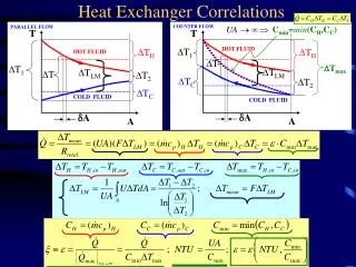
By: Dr. M.R.Shahnazari LMTD CORRECTION FACTOR
By: Dr. M.R.Shahnazari SAMPLE CORRECTION FACTOR • one shell pass; two or more even
By: Dr. M.R.Shahnazari TUBE SIZE: : Birmingham Wire Gage
By: Dr. M.R.Shahnazari TUBE PATTERN
By: Dr. M.R.Shahnazari TUBE PITCH
By: Dr. M.R.Shahnazari Why a Shell and Tube Heat Exchanger? • Shell and tube heat exchangers are the most widespread and commonly used basic heat exchanger configuration in the process industries. • The reasons for this general acceptance are several. • The shell and tube heat exchanger provides a comparatively large ratio of heat transfer area to volume and weight. • It provides this surface in a form which is relatively easy to construct in a wide range of sizes.
By: Dr. M.R.Shahnazari Better Concurrence…. • It is mechanically rugged enough to withstand normal shop fabrication stresses, shipping and field erection stresses, and normal operating conditions. • The shell and tube exchanger can be reasonably easily cleaned, and those components most subject to failure - gaskets and tubes – can be easily replaced. • Shop facilities for the successful design and construction of shell and tube exchangers are available throughout the world.
By: Dr. M.R.Shahnazari Simple Shell & Tube Heat Exchanger
By: Dr. M.R.Shahnazari Inner Details of S&T HX
By: Dr. M.R.Shahnazari Components of STHEs • It is essential for the designer to have a good working knowledge of the mechanical features of STHEs and how they influence thermal design. • The principal components of an STHE are: • shell; shell cover; • tubes; tubesheet; • baffles; and nozzles. • Other components include tie-rods and spacers, pass partition plates, impingement plate, longitudinal baffle, sealing strips, supports, and foundation.
By: Dr. M.R.Shahnazari Types of Shells
By: Dr. M.R.Shahnazari Fixed tube sheet
By: Dr. M.R.Shahnazari U-Tube STHE
By: Dr. M.R.Shahnazari Floating Head STHE TEMA S
By: Dr. M.R.Shahnazari Floating Head STHE TEMA T
By: Dr. M.R.Shahnazari Cross Baffles • Baffles serve two purposes: • Divert (direct) the flow across the bundle to obtain a higher heat transfer coefficient. • Support the tubes for structural rigidity, preventing tube vibration and sagging. • When the tube bundle employs baffles, • the heat transfer coefficient is higher than the coefficient for undisturbed flow around tubes without baffles. • For a baffled heat exchanger the higher heat transfer coefficients result from the increased turbulence. • the velocity of fluid fluctuates because of the constricted area between adjacent tubes across the bundle.
By: Dr. M.R.Shahnazari Types of Baffle Plates : Segmental Cut Baffles • The single and double segmental baffles are most frequently used. • They divert the flow most effectively across the tubes. • The baffle spacing must be chosen with care. • Optimal baffle spacing is somewhere between 40% - 60% of the shell diameter. • Baffle cut of 25%-35% is usually recommended.
Double Segmental Baffles Triple Segmental Baffles By: Dr. M.R.Shahnazari Types of Baffle Plates The triple segmental baffles are used for low pressure applications.
By: Dr. M.R.Shahnazari Types of Baffle Plates
By: Dr. M.R.Shahnazari Types of Baffle Plates Disc and ring baffles are composed of alternating outer rings and inner discs, which direct the flow radially across the tube field. § The potential bundle-to-shell bypass stream is eliminated § This baffle type is very effective in pressure drop to heat transfer conversion
By: Dr. M.R.Shahnazari Therm-Hydraulic Analysis of Heat Exchanger • Initial Decisions. • Tube side Thermal Analysis. • Thermal analysis for Shell side. • Overall Heat Transfer coefficient. • Hydraulic Analysis of Tube side. • Hydraulic Analysis of Shell side.
By: Dr. M.R.Shahnazari Fluid Allocation : Tube Side • Tube side is preferred under these circumstances: • The higher velocities will reduce buildup • Mechanical cleaning is also much more practical for tubes than for shells. • Corrosive fluids are usually best in tubes • Tubes are cheaper to fabricate from exotic materials • This is also true for very high temperature fluids requiring alloy construction • Toxic fluids to increase containment • Streams with low flow rates to obtain increased velocities and turbulence • High pressure streams since tubes are less expensive to build strong. • Streams with a low allowable pressure drop
By: Dr. M.R.Shahnazari Fluid Allocation : Shell Side • Shell side is preferred under these circumstances: • Viscous fluids go on the shell side, since this will usually improve the rate of heat transfer. • On the other hand, placing them on the tube side will usually lead to lower pressure drops. Judgment is needed. • Low heat transfer coefficient: • Stream which has an inherently low heat transfer coefficient (such as low pressure gases or viscous liquids), this stream is preferentially put on the shell-side so that extended surface may be used to reduce the total cost of the heat exchanger.
By: Dr. M.R.Shahnazari General design consideration
By: Dr. M.R.Shahnazari Flow Past Tube Bundles : Outside Film Coefficient
By: Dr. M.R.Shahnazari Major Steps in Design • Initial Decisions. • Tube side Thermal Analysis. • Thermal analysis for Shell side flow. • Overall Heat Transfer coefficient. • Hydraulic Analysis of Tube side. • Hydraulic Analysis of Shell side.
By: Dr. M.R.Shahnazari Initial Decisions • Spatial allocation of fluid. • Determination of flow velocity. • Initial guess for number of tubes. • Correction for standard tube diameter. • Effect of number of tubes on tube length….
By: Dr. M.R.Shahnazari Avoid Developed Flow
By: Dr. M.R.Shahnazari Thermal Analysis of Heat Exchanger • Known as heat exchanger specification problems and their solutions. • These are ‘rating’, ‘design’, and ‘selection’.
By: Dr. M.R.Shahnazari Rating Analysis • The rating problem is evaluating the thermo-hydraulic performance of a fully specified exchanger. • The rating program determines: • the heat transfer rate and the fluid outlet temperatures for prescribed fluid flow rates, inlet temperatures, and • the pressure drop for an existing heat exchanger; • therefore the heat transfer surface area and the flow passage dimensions are available.
By: Dr. M.R.Shahnazari The Rating Analysis
By: Dr. M.R.Shahnazari The Design (Sizing) Analysis • ‘Design’ is the process of determining all essential constructional dimensions of an exchanger that must perform a given heat duty and respect limitations on shell-side and tube-side pressure drop. • In the Design (sizing) Analysis, • An appropriate heat exchanger type is selected. • The size to meet the specified hot and cold fluid inlet and outlet temperatures, flow rates, and pressure drop requirements, is determined. • Constraints: • Minimum or maximum flow velocities, • Size and/or weight limitations, • Ease of cleaning and maintenance, erosion, tube vibration, and thermal expansion. • Each design problem has a number of potential solutions, but only one will have the best combination of characteristics and cost.
By: Dr. M.R.Shahnazari Basic Design Procedure
By: Dr. M.R.Shahnazari Basic Design Procedure • Heat exchanger must satisfy the Heat transfer requirements (design or process needs) • Allowable pressure drop (pumping capacity and cost) • Steps in designing a heat exchanger can be listed as: • Identify the problem • Select an heat exchanger type • Calculate/Select initial design • parameters • Rate the initial design • Calculate thermal performance and pressure drops for shell and tube side. • Evaluate the design. • Is performance and cost acceptable?
By: Dr. M.R.Shahnazari The Selection Analysis • ‘Selection’ means choosing a heat exchanger from among a number of units already existing. • Typically, these are standard units listed in catalogs of various manufacturers. • Sufficient manufacturer’s data usually exist to allow one to select comfortably oversized exchanger with respect to both area and pressure drop.
By: Dr. M.R.Shahnazari Thermal Analysis for Shell-Side • Conventional Methods are based on Non-dimensional Analysis… • Convection Heat Transfer demands Definition of • Nusselt Number – Output • Reynolds Number – Input • Prandtl Number -- Input
By: Dr. M.R.Shahnazari Shell Side Fluid Flow
By: Dr. M.R.Shahnazari Shell-Side Reynolds Number Reynolds number for the shell-side is defined based on the equivalent diameter and the velocity based on a reference flow:
By: Dr. M.R.Shahnazari Simplified Classification of Shell Side Flow
By: Dr. M.R.Shahnazari Fluid dynamic Similarity of Counter & Cross Flow Heat Transfer ?!?!?!
By: Dr. M.R.Shahnazari Tube Layout & Flow Structure A Real Use of Wetted Perimeter !