Download
1 / 29
290 likes | 425 Views
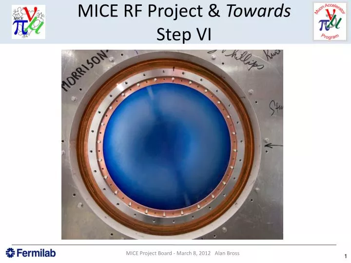
MICE RF Project & Towards Step VI. MICE Step VI. RF Cavities for MICE . X 2. A Review: 201 MHz Cavity Test Treating NCRF cavities with SCRF processes. The 201 MHz Cavity – Achieved 21 MV/m Design gradient – 16MV/m At 0.75T reached 10-12 MV/m. However, No observed damage!.

E N D
MICE RF Project & Towards Step VI MICE Project Board - March 8, 2012 Alan Bross
MICE Step VI MICE Project Board - March 8, 2012 Alan Bross
RF Cavities for MICE X 2 MICE Project Board - March 8, 2012 Alan Bross
A Review: 201 MHz Cavity TestTreating NCRF cavities with SCRF processes • The 201 MHz Cavity – Achieved 21 MV/m • Design gradient – 16MV/m • At 0.75T reached 10-12 MV/m However, No observed damage! MICE Project Board - March 8, 2012 Alan Bross
MICE Prototype Cavity ConditioningIt didn’t Design Gradient MICE Project Board - March 8, 2012 Alan Bross
201 MHz Cavity Running Limited by RF Power MICE Project Board - March 8, 2012 Alan Bross
201 MHz PrototypeSpark damage -None Note: Stored energy available to sparks » 100J (100X that of 805) MICE Project Board - March 8, 2012 Alan Bross
Coupler CeramicCu migration TiN Coated Ceramic MICE Project Board - March 8, 2012 Alan Bross
Production Cavity Status • Ten RF cavities (two spares) at LBNL now • All 11 beryllium windows received at LBNL • Ten ceramic RF windows • Six tuner flexures are being fabricated at Fermilab (DONE) • Components for 6 actuators are being fabricated • RF loop coupler design has been updated to eliminate the gap between the outer coax and the RF loop & clearance issues to the body port • Fabrication of fixturing complete • Preparation of the cavity surface: mechanical smoothing • EP preparation in progress at LBNL • Delays due to safety review • EP to start after the ES & H approval. • Measurements of the remaining six cavities to start after EP; • Each cavity will be tuned to a center frequency after EP. MICE Project Board - March 8, 2012 Alan Bross
RF – Single Cavity System Test (SCTS)For tests in the MTA On track for start of assembling this system in May • Vacuum vessel delivered • Tuners complete • Actuators in production • New couplers due – early May MICE Project Board - March 8, 2012 Alan Bross
SCTS • Check engineering and mechanical design • Fully define the fabrication process • Incorporate any design changes into the RFCC vacuum vessel design • Test of the RF tuning system with 6 tuners and actuators on a cavity and verify the frequency tuning range • Obtain hands-on experience on assembly and procedures MICE Project Board - March 8, 2012 Alan Bross
SCTS II • Cavity installation • Develop fixturing for inserting the cavities into the vacuum vessel • Beryllium windows • RF couplers and connections • Water cooling pipe connections • Vacuum port and connections • Tuners and actuator circuit • Mounting and alignment of the tuners onto the cavity is critical to alignment of the cavity in the vacuum vessel • Alignment of actuator (through the vacuum vessel wall) to the tuner is important MICE Project Board - March 8, 2012 Alan Bross
SCTS III • Aligning cavity with hexapod support struts • Test developed MathCAD alignment software program • Vacuum vessel support and handling • Verify operation of the getter vacuum system • Investigate RF processing of MICE cavities • Test with RF power • Explore max stable operating regime • Test MICE RF power delivery components (waveguides, etc). • Can test operation at LN2 temperature MICE Project Board - March 8, 2012 Alan Bross
MICE RFCCliteTest in MTA MICE Project Board - March 8, 2012 Alan Bross
MICE RF Power Systems MICE Project Board - March 8, 2012 Alan Bross
RF system components Master Oscillator Controls etc DL Test System At present Not found 300 kW Amplifier 300 kW Amplifier 300 kW Amplifier 300 kW Amplifier Auxiliary Systems Auxiliary Systems 2 MW Amplifier 2 MW Amplifier HT Supplies 2 MW Amplifier 2 MW Amplifier HT Supplies Daresbury LBNL CERN 201 MHz Cavity Module 201 MHz Cavity Module
Amplifier status • Refurbishment of LBNL and CERN RF components: • First medium power (250 kW) amplifier and power supply system tested 2008 • Refurbishment and rebuild of first high power (2 MW) amplifier complete October 2009 • Power supplies for first 2 MW amp operational • Two further 300 kW amplifiers awaiting repair • Two refurbished 2 MW CERN amplifiers partly tested, awaiting assembly and high power test • Need to build 3 more sets of power supplies • One more 300kW amplifier to buy/acquire
RF Power Distribution MICE Project Board - March 8, 2012 Alan Bross
Status/Plan of RF Power System • Amplifier test system tested to 1 MW with power supplies; • Coax system designed to phase match RF into each cavity, all coax lines are the same length and have the same number of elbows; • Hybrids will be used to split RF power and give good isolation, reject load can be small as balanced reflected; power will be directed back to triode, this should not present an issue; • Cavity phasing can be done using a combination of LLRF and limited range high power phase shifters; • Nitrogen gas pressure will be used to extend the peak voltage stand off of the coax guides. MICE Project Board - March 8, 2012 Alan Bross
External RF Review Panel Report • Tube lifetime is around 15,000 hours on ISIS at 50 Hz ~ 4MW • MICE will run at 1Hz and 2MW so lifetime should be extended • Power output will degrade over time to around 50% of initial level, therefore the effective cavity gradient will also degrade over time • Currently no spare tubes • Option to purchase 2 more TH116 tubes, however there will be no more, production of glass assemblies has ended • ISIS tubes are removed from service at power level of ~1MW • Amplifiers will be difficult to maintain behind shield wall • Layout changes suggested to allow access to work on systems • 4616 amplifier currently appears above shield wall and may see some magnetic field – no information found on what level is acceptable from manufactures or other lab experiments, however as the tube has a very small electron drift gap • Not that concerned at the moment, will have to fix what goes wrong in the hall. Power supplies include many transformers, circuit breakers, PLCs and many other magnetic components MICE Project Board - March 8, 2012 Alan Bross
Cavity Filling Issue • Using a slow fill approach, the forward power is switched on in a ramped way to reduce reflected power effect • Can reduce reflected power to a tenth of forward wave • Example from FNAL • Using digital LLRF this is simple to achieve • Nitrogen will be used in the coax guides • SF6 also option, used routinely in MTA MICE Project Board - March 8, 2012 Alan Bross
RF Power System - Summary • RF testing to 2MW will be done before August, 2012 • RF review has prompted a new round of optimisation of coax distribution that looks to make things easier in a number of areas, space around the amplifiers, lower transmission loss, easier to install • Coax should be filled with N2, slow cavity filling will be needed to avoid breakdown inside the guides, RF tests at the MTA are required to prove this as an acceptable design • RF specification is being refined and needs to be approved • Discussions about LLRF control/experiment timing need to be understood and build a team to look at solutions MICE Project Board - March 8, 2012 Alan Bross
Moving Towards MICE Step VI MICE Project Board - March 8, 2012 Alan Bross
Towards Step VI • The following schedule is not resource loaded [So you know what quality factory to apply] , but is based on detailed estimates from Fermilab’s Technical Division (for coil tests), Qi Huan Company (parts fab & coil winding), Meyer Tool (cryostat assembly & vacuum test) and MICE’s current understanding of our technical progress. • I have added a 30% float to the Fermilab work on testing/training the windings • Final CC magnet assembly time is based on a preliminary estimate by Vladimir Kashikhin • I have requested that Fermilab PPD-TD make a first pass at a detailed estimate • No commitment from Fermilab to do this job at this moment • I have used the latest input from Derun Li and Steve Virostek regarding fabrication times at Qi Huan and HIT and logistics in China & between China and the US • This plan also assumes that a second Coupling Coil magnet assembly area/team is operational (Currently under discussion with interested parties) which adds flexibility w/r to manpower availability • And given the modular nature of the coupling coil magnet (next talk), distributing the assembly work is possible. • In addition it does not include details of installation and commissioning of the RF power system at RAL • It does not include all components (& how all is funded), but it presents a first draft at developing a full plan to meet the MICE target date of 2016 for starting Step VI MICE Project Board - March 8, 2012 Alan Bross
MICE Step VISchedule uncertainties • Coupling coils constitute the major schedule driver • Tests results from first winding crucial • Release Qi Huan to produce more • Releasing drawings for fabrication • However: • The RF power system installation is a very large task and stresses MICE resource availability • Particularly in the UK (start of installation interleaved with Step IV running) • The availability of UK funding for the last AFC and LH2 system is at present uncertain • FY13 funding in the US at the moment looks “dire” MICE Project Board - March 8, 2012 Alan Bross
Conclusions • A test of the production MICE RF cavities is on schedule to begin this summer in the MuCool Test Area at Fermilab • This will test all aspects of MICE cavity operation and can test at gradients much higher than will be seen in MICE • Although not in the final B field configuration • Preparations are well along to have a new test facility (Solenoid Test Facility) ready to begin testing the first MICE CC winding this summer at Fermilab • We have a preliminary estimate for fabrication of the CC cryostats and expect to be able to begin their procurement process this FY(US) • This first detailed look at large parts of the Step VI schedule lends credibility to our Target 2016 start within the caveats as indicated MICE Project Board - March 8, 2012 Alan Bross