Download
1 / 46
520 likes | 960 Views
Diodes, Triodes, Thermistors, Opto-isolators, & Phototransistors. ME 6405 – Spring 2005 Danny Nguyen Wei Tan Qiulin Xie. Presentation Outline. Diodes – Danny Triacs & Thermistors – Qiulin Opto-isolators & Phototransistors – Wei. Diodes: Overview. Meet the Diode Junction Diodes

E N D
Diodes, Triodes, Thermistors, Opto-isolators, & Phototransistors ME 6405 – Spring 2005 Danny Nguyen Wei Tan Qiulin Xie
Presentation Outline • Diodes – Danny • Triacs & Thermistors – Qiulin • Opto-isolators & Phototransistors – Wei
Diodes: Overview • Meet the Diode • Junction Diodes • Analysis and Applications • Zener Diodes and Applications
What is a Diode? • Simplest semiconductor device • Allows current to flow in one direction but not the other • Symbols:
Junction Diodes • Start out with Silicon or Germanium (Group IV elements) • P-type - doping with Group III elements • Boron, Aluminum, Gallium • Adds positive ‘holes’ to the region • N-type - Group V doping • Phosphorous, Arsenic • Add electrons to the region
Junction Diodes • Due to thermal energy, some electrons diffuse into the p-type region, creating a depletion region • No current flows through the diode at this point
Junction Diodes • Forward Bias • Depletion region decreases • Current flow when voltage is high enough (0.6-0.7 Volts) • Current sustained by majority carriers
Junction Diodes • Reverse Bias • Depletion region increases • Small leakage current by minority carriers • Reverse saturation current (I0) • On the order of 10-9to 10-15 A
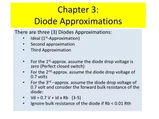
V [ ( ) ] q D I I I V V V I V V V I I V V 0 0 0 0 6 0 0 0 7 0 1 · · ¡ > > e x p = = = = = = » D D D D D D D D D 0 o n o n o n k T ; ; ; : ; : Analysis of Diodes • Mathematical Model • Ideal Model • On: Off: • Constant Voltage Drop Model • On: • Off:
Analysis and Applications • Half-wave rectifier • CVD Analysis: • On: Replace diode with Von voltage source • Off: Replace diode with open circuit
V V I V V V 0 7 0 0 7 ¡ > > ! = D i i o : ; : Analysis and Applications • Half-wave rectifier • CVD Analysis: • On: • Off:
V V V V I I V V V V V 0 0 7 7 0 0 0 0 7 · ¡ > > = ! ! = = D D i i i o o : : ; ; : Analysis and Applications • Half-wave rectifier • CVD Analysis: • On: • Off:
Analysis and Applications • Full-wave bridge rectifier • Peak Detector
Zener Diodes • Operated by reverse bias instead of forward bias • All diodes have a breakdown region – point where the diode can not handle anymore negative voltage • Voltage remains nearly constant in the breakdown region (Vz: Zener Voltage) under widely varying current for Zeners
Zener Diodes: I-V Graph Reverse Breakdown Model Schematic
k k V V R R V V 6 2 1 1 0 7 1 1 = = = = » L i z : ; ; ; Zener Diodes: Applications • Ability to maintain a constant voltage allows it to act as a voltage regulator
Zener Diodes: Specifications • VZ (Zener Voltage): Common range is between 3.3V and 75V • Tolerance: Commonly 5 to 10% • Power Handling: ¼, ½, 1, 5, 10, 50 W
Contents • Shockley Diode • Silicon-Controlled Rectifier (SCR) • Triac • Thermistor
Shockley Diode • Shockley diode after its inventor, William Shockley • four-layer diode, also known as a PNPN • on if applying sufficient voltage between anode and cathode • Off if reducing to a much lower voltage
Silicon-Controlled Rectifier (SCR) • Shockley diode becomes SCR if gate addition to PNPN • it behaves exactly as a Shockley diode If an SCR's gate is left disconnected. • gate terminal may be used as an alternative means to latch the SCR • SCRs are unidirectional (one-way) current devices, making them useful for controlling DC only
Triode AC Switch (Triac) • A triac can be regarded as a "bidirectional (AC) SCR” because it conducts in both directions. • 5 layer device • Region between MT1 and MT2 are parallel switches (PNPN and NPNP) • Allows for positive or negative gate triggering
Triac Characteristic Curve • VDRM refers to the maximum peak forward voltage which may be continuously applied to the main terminals and the highest voltage that can be blocked • IDRM is the leakage current of the Triac when VDRM is applied to MT1 and MT2 , which is several orders of magnitude smaller than the “on” rating • VRRM: Peak Repetitive Reverse Voltage Maximum peak reverse voltage that may be continuously applied to the main terminals • IGT Gate trigger current • VGT Gate trigger voltage • Latching Current: the value of on-state current required to maintain conduction at the instant when the gate current is removed • Holding current :Value of on-state current required to maintain conduction once the device has fully turned on and the gate current has been removed. The on-state current is equal to or lower in value than the latching current
Triac Advantages and Applications • Advantages • Controllable trigger • Four quadrant device • Triacs provide the lowest cost and simplest route to reliable, interference-free switching and power control. • Application • Light dimmer control • Motor speed control (a phase-control circuit is used to vary the power to brush motors.) • Reason • Trigger pulse can control any percentage of half cycle
Thermistor • Thermistor - Temperature sensitive resistor • Their change in electrical resistance is very large and precise when subjected to a change in temperature. • Thermistors exhibit larger parameter change with temperature than thermocouples and Resistance Temperature Detectors (RTD’s). • Thermistor - sensitive • Thermocouple - versatile • RTD – stable • Generally composed of semiconductor materials. • Very fragile and are susceptible to permanent decalibration.
Thermistor Probe • One of many available probe assemblies
Thermistor Characteristics • Most thermistors have a negative temperature coefficient (NTC); that is, their resistance decreases with increasing temperature. • Positive temperature coefficient (PTC) thermistors also exist with directly proportional R vs. T. • Extremely non-linear devices (high sensitivity) • Common temperature ranges are –100 °F (~-75 °C) to +300 °F (~150 °C) • Some can reach up to 600 °F
= Thermistor R-T Curve • An individual thermistor curve can be very closely approximated by using the Steinhart-Hart equation: T = Degrees Kelvin R = Resistance of the thermistor A,B,C = Curve-fitting constants • Typical Graph Thermistor (sensible) V or R RTD (stable) Thermocouple (versatile) T
variable resistor for setting desired temperature relay thermistor high gain amplifier Thermistor Applications Temperature Control • Resistor is set to a desired temperature (bridge unbalance occurs) • Unbalance is fed into an amplifier, which actuates a relay to provide a source of heat or cold. • When the thermistor senses the desired temperature, the bridge is balanced, opening the relay and turning off the heat or cold.
Phototransistor • Introduction • Package and Scheme • Operation • Advantages • Example and applications
Phototransistor Introduction • A transistor which is sensitive to the input light intensity • Operation similar to traditional transistors; Have collector, emitter, and base • Phototransistor base is a light-sensitive collector-base junction • Dark Current: Small collector can emit leakage current when transistor is switched off.
Phototransistor Scheme • Photocurrent: The electrons are amplified by the transistor and appear as a current in the collector/emitter circuit. • The base is internally left open and is at the focus of a plastic lens.
Phototransistor Operation • The phototransistor must be properly biased • A light sensitive collector base p-n junction controls current flow between the emitter and collector • As light intensity increases, resistance decreases, creating more emitter-base current • The small base current controls the larger emitter-collector current • Collector current depends on the light intensity and the DC current gain of the phototransistor
Why Use Phototransistors? • More sensitive than photodiodes of comparably sized area • Available with gains form 100 to over 1500 • Moderately fast response times • Available in a wide range of packages • Usable with almost any visible or near infrared light source such as IREDs, lasers, sunlight, and etc • Same general electrical characteristics as familiar signal transistors
Automated Cart LED Baffle Phototransistor Obstacle Application Example: Avoiding Obstacles
Phototransistor Applications • Computer/Business Equipment • Write protect control – floppy driver • Margin controls – printers • Industrial • LED light source – light pens • Security systems • Consumer • Coin counters • Lottery card readers
Optoisolator • Introduction • Scheme and Package • Optocoupler Interrupter Example • Advantages and applications
Optoisolator Introduction • A device that uses a short optical transmission path to accomplish electrical isolation between elements of a circuit. Note 1: The optical path may be air or a dielectric waveguide; Note 2: The transmitting and receiving elements may be contained within a single compact module.
Optoisolator Scheme • The light emitted form the LED is detected by a photodetector which sits across from the LED inside the chip, and output a current. • Since the input signal is passed from the LED to the photodetector, and cannot be passed form the photodetector to the LED, the input device is optically isolated from the circuit connected to the output side.
Optoisolator Package • An IRED is typically a controllable light source and a phototransistor employs as the detector element. • The input and output sides have separate grounds • Optoisolators sensitive to input voltages.
Optocoupler Interrupter Example • Integrated emitter and detector pair • Setup Similar to Lab L3 • Used to calculate speed or distance
Optoisolator Advantages & Applications • Advantages • Output signals have no effect on input • High reliability and high efficiency • Noise isolation • Small size • Applications • Optical switch • Signal transmission devices • Used to control motors, solenoids, etc.
References • “Introduction to Mechatronics and Measurement Systems, 2nd Ed.” by D.G. Alciatore and M.B. Histand • http://www.semiconductors.philips.com • http://www.omega.com • “Microelectronic Circuit Design, 1st Ed.” by Richard C. Jaeger • Fall 2000 Slides


![G6 - CIRCUIT COMPONENTS [3 exam question - 3 groups]](https://cdn1.slideserve.com/2780393/g6-circuit-components-3-exam-question-3-groups-dt.jpg)