Download
1 / 32
320 likes | 611 Views
Study of cooled PWO Crystal. Alexander Toropin New York University. Introduction.

E N D
Study of cooled PWO Crystal Alexander Toropin New York University
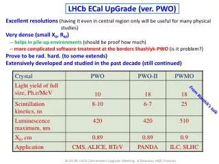
Introduction • A preliminary study of BGO crystals with Hamamatsu APD readout has shown these crystals could be used as detector elements for the MECO electromagnetic calorimeter. At room temperature, using cosmic muons, ~87 photoelectrons per MeV of energy loss were collected in a single diode. Those measurements were made with a shaping time ~1 ms long. A more recent study with a 50 ns shaper gives ~50 pe/MeV/diode. • Disadvantages of BGO crystals: high price and long decay time ~300 ns. • Another possible choice for the crystal is PWO (PbWO4). These crystals were chosen for the electromagnetic calorimeters of forthcoming experiments at CERN LHC (CMS, ALICE). They are cheaper, have decay time ~15 ns, and higher density than BGO. • Disadvantage: low light yield ~3 pe/MeV for Hamamatsu APD (CMS data) • Possible solutions: 1) Use the large area APDs. RMD APD with sensitive area 13x13 mm2 and quantum efficiency ~55% can increase light yield ~5 times compared to Hamamatsu APD (5x5 mm2 and 75% QE) . 2) Cooling the crystals to temperature about –20oC. Light yield could be increased in ~2.3 times (P.Lecoq et al., NIM A365(1995) 291-298). Alexander Toropin NEW YORK UNIVERSITY
Parameters of RMD APD Alexander Toropin NEW YORK UNIVERSITY
Experimental setup A schematic side view of experimental setup to study the crystal response to cosmic muons is shown below SC1 = 12 x 0.5 x 50 cm3 SC2 = 3 x 1 x 11 cm3 PWO = 3 x 3 x 14 cm3 SC3 = 3 x 1 x 11 cm3 Alexander Toropin NEW YORK UNIVERSITY
Readout chain The readout chain consisted of • preamplifier CR-101D (CREMAT, http://www.cremat.com) , • an amplifier-shaper with shaping time ~200 ns, • a VME resident 12-bit peak sensitive ADC (CAEN V785). The VME crate was interfaced to PC running WINDOWS 98 operating system. DAQ program was written for the ROOT (http://root.cern.ch) environment. The data was plotted as it was received and stored event by event on the PC hard disk. Alexander Toropin NEW YORK UNIVERSITY
PWO with RMD APD. Room temperature. The cosmic muons spectrum at room temperature is shown below . The curve superimposed on this plot is a fit to a Gaussian distribution. Alexander Toropin NEW YORK UNIVERSITY
PWO with RMD APD. Room temperature. The number of primary photoelectrons collected by RMD APD from PWO crystal at room temperature can be estimated from these measurements where 51.43 is the mean value of the previous spectrum obtained from a fit to a Gaussian distribution, 0.977x10⁻³ is a coefficient to convert ADC counts to Volts, 1.927 is the electronics chain calibration coefficient in Volt/pCoul, 6.2x10¹⁸ is the electronic charge in Coul, 300 is the APD gain, 35 MeV is the MPV value of simulated energy spectrum produced by cosmic muons in PWO crystal and fitted to Landau distribution Alexander Toropin NEW YORK UNIVERSITY
Cosmic muons spectrum at 7o C The cosmic muons spectrum at 7o C is shown below. To collect data for this spectrum a small office refrigerator was used. Alexander Toropin NEW YORK UNIVERSITY
Cosmic muons spectrum at –24oC For further cooling was used the freezer of a GE refrigerator. The view of experimental setup is shown below Alexander Toropin NEW YORK UNIVERSITY
Cosmic muons spectrum at –24oC The view of experimental setup inside freezer Alexander Toropin NEW YORK UNIVERSITY
Cosmic muons spectrum at –24oC The temperature inside the freezer chamber was monitored by an external digital thermometer and a thermistor connected to an ADC through special circuit. The cosmic muons spectrum versus temperature is shown below Alexander Toropin NEW YORK UNIVERSITY
Cosmic muons spectrum at –24oC The profile of amplitude of signals versus temperature is shown below. This plot was fitted to a third order polynomial to make a temperature correction function. Alexander Toropin NEW YORK UNIVERSITY
Cosmic muons spectrum at –24oC The cosmic muons spectrum after temperature corrections is shown below Alexander Toropin NEW YORK UNIVERSITY
Cosmic muons spectrum at –24oC The same spectrum without temperature corrections and with pedestals peak is shown below. The pedestals were collected together with signals due to inefficiency of trigger and it reflected the electronics noise during run period (~6days). Pedestals peak was fitted to Gaussian distribution. Alexander Toropin NEW YORK UNIVERSITY
Cosmic muons spectrum at –24oC The cosmic muons spectrum without temperature corrections is shown below. The curve superimposed on this plot is the same spectrum after the temperature corrections. All amplitudes were normalized to –24oC. Alexander Toropin NEW YORK UNIVERSITY
Cosmic muons spectra at +22oC and –24oC For comparison the cosmic muons spectra at +22oC and –24oC are shown. Alexander Toropin NEW YORK UNIVERSITY
Cosmic muons spectrum at –24oC The number of primary photoelectrons per MeV of energy loss could be estimated as where 93.63 is the MPV value of the previous spectrum fitted to Landau distribution, 0.977x10⁻³ is a coefficient to convert ADC counts to Volts, 1.708 is the electronics chain calibration coefficient in Volt/pCoul, 6.2x10¹⁸ is the electronic charge in Coul, 300 is the APD gain, 35 MeV is the MPV value of simulated energy spectrum produced by cosmic muons in PWO crystal and fitted to Landau distribution Alexander Toropin NEW YORK UNIVERSITY
Number of photoelectrons from Webb plot The number of photoelectrons collected by the APD can be estimated from the signal width once the excess noise factor is determined. The signal width is the sum of photostatistical and noise fluctuations (A.Karar et al., NIM A428(1999) 413-431) where is the number of primary photoelectrons, , is the gain of APD, is the signal amplitude, is the excess noise factor, is the charge measured at the input of preamplifier, is the r.m.s. of electronics noise (pedestal width) Alexander Toropin NEW YORK UNIVERSITY
Number of photoelectrons from Webb plot From McIntyre theory of multiplication process in semiconductor devices excess noise factor could written as where , is the ionization probability per unit of length for electrons and for holes, is the gain of APD. For is possible to write and The left term of this equation could be plotted as a function of (Webb plot). This plot is shown on the next page. Alexander Toropin NEW YORK UNIVERSITY
Webb plot To produce this plot the Blue LED light was adjusted to have the same peak amplitude as MPV of experimental spectrum for M = 300. In this case we can assume we have the same number of primary photoelectrons. Additional points in this plot were produced by varying the APD gain. Alexander Toropin NEW YORK UNIVERSITY
Number of photoelectrons from Webb plot The Webb plot was fitted to straight line. The intercept of this line with vertical axis gives the number of primary photoelectrons and for gain This estimation relies on the points at low gain that have larger statistical errors. Alexander Toropin NEW YORK UNIVERSITY
Number of photoelectrons estimated with fixed gain by varying the LED signals. More accurate estimation the number of primary photoelectrons could be done by varying the amplitude of LED signals with fixed APD gain. We can suppose the number of primary photoelectrons is proportional to the intensity of LED light. In this case M and F were fixed. For each LED signal the number of primary photoelectrons corresponding to the experimental spectrum could be defined as where is the MPV value from experimental spectrum fitted to Landau distribution. The corresponding plot is shown on the next page. From that plot the number of primary photoelectrons is Alexander Toropin NEW YORK UNIVERSITY
Number of photoelectrons estimated with fixed gain by varying LED signals. To produce this plot, gain was fixed. Each point had different intensity of LED signal and was normalized to the MPV value of experimental cosmic muons spectrum at temperature –24oC. Alexander Toropin NEW YORK UNIVERSITY
Cosmic muons spectrum with 50 ns shaper. For comparison purposes the signal after preamplifier was divided between two shapers with 50 and 200 ns shaping times. All results presented above were produced with 200 ns shaper. The cosmic muons spectrum with 50 ns shaper and temperature corrections is shown below. Alexander Toropin NEW YORK UNIVERSITY
Cosmic muons spectrum with 50 ns shaper. From the previous plot the number of primary photoelectrons per MeV of energy loss could be estimated as where 124.4 is the MPV value of the previous spectrum fitted to Landau distribution, 0.977x10⁻³ is a coefficient to convert ADC counts to Volts, 4.325 is the electronics chain calibration coefficient in Volt/pCoul, 6.2x10¹⁸ is the electronic charge in Coul, 300 is the APD gain, 35 MeV is the MPV value of simulated energy spectrum and fitted to Landau distribution. The number of primary photoelectrons is 2 times less than in the case of 200 ns shaper because CR-101D preamplifier is not enough fast for this shaper. This number could be improved by using preamplifier with shorter rise time with compare to CR-101D. Alexander Toropin NEW YORK UNIVERSITY
Estimation of energy resolution In this setup cosmic muons crossed the crystal from side to side (path length ~3 cm) and had energy loss ~35 MeV. In MECO calorimeter, electrons will cross the crystal along its axis and will lose ~100 MeV. From presented data for 200 ns shaper, the contributions to energy resolution due to photostatistics and electronics noise are • due to photostatistics • due to electronics noise and here 35 is the approximate number of primary photoelectrons, 1.97 is r.m.s. of pedestals distribution in ADC counts, 93.64 is MPV of cosmic muons spectrum in ADC counts, 100 MeV is expected energy loss Alexander Toropin NEW YORK UNIVERSITY
Brief study of signal shapes The cooling procedure increases light yield from PWO crystal but crystal response becomes more slow. To check crystal response a fast photomultiplier tube Amperex XP 2230B was used. • To estimate a shape of PMT signal a small piece of scintiliator with dimensions 2.5x2.5x0.8 cm3 was connected to its window. • Cosmic muons were used as the incident particles. • After calibration the PMT was connected to PWO crystal. • The same procedures were made at temperatures 22OC and -24OC. • For comparison purpose the response from BGO crystal at 22OC was shown. The corresponding pictures are shown below. Alexander Toropin NEW YORK UNIVERSITY
Calibration PMT+SC PMT + scintillator at -24OC. PMT + scintillator at +22OC. Alexander Toropin NEW YORK UNIVERSITY
PMT+PWO PWO at –24oC PWO at +22oC Alexander Toropin NEW YORK UNIVERSITY
PMT+BGO, 22oC The shape of the signal from BGO crystal at room temperature. This picture has 10 times wider scale. Alexander Toropin NEW YORK UNIVERSITY
Conclusions • Cooling the RMD APD considerably reduces the Dark Current. • Cooling the PWO crystal increases its light yield. At –24oC ~35 photoelectrons per MeV per RMD APD were measured with a shaping time of 200 ns. • Cooling the PWO crystal makes its output slower. • The contribution to the energy resolution from photostatistics and electronics noise is ~2.5%, using one RMD APD. Alexander Toropin NEW YORK UNIVERSITY
Future plans • Continue study of cooled PWO crystal with 2 RMD APDs connected to the edge of the crystal to investigate possibility the energy resolution estimation by looking for the differences in amplitudes of two signals. • Study of the RMD APD response in the system APD+WLS+PWO, where WLS is Wave Length Shifter. • Study of cooled PWO crystal with new fast preamplifier. • Prepare a matrix (3x3 or 4x4) of PWO crystals with cooling system to make study by BNL test beam. • Brief study of small sizes crystals LSO and YSO. Alexander Toropin NEW YORK UNIVERSITY