Download
1 / 30
300 likes | 497 Views
Present activities on LHD-type Reactor Designs FFHR. National Institute for Fusion Science, Japan. Contributed with S. Imagawa, O. Mitarai * , T. Dolan, T. Tanaka, Y. Kubota, K. Yamazaki, K. Y. Watanabe, N. Mizuguchi, T. Muroga, N. Noda, O. Kaneko, H. Yamada, N. Ohyabu,

E N D
Present activities on LHD-type Reactor Designs FFHR National Institute for Fusion Science, Japan Contributed with S. Imagawa, O. Mitarai*, T. Dolan, T. Tanaka, Y. Kubota, K. Yamazaki, K. Y. Watanabe, N. Mizuguchi, T. Muroga, N. Noda, O. Kaneko, H. Yamada, N. Ohyabu, T. Uda, A. Komori, S. Sudo, and O. Motojima Akio SAGARA, Japan-US Workshop on Fusion Power Plants and Related Advanced Technologies with participation of EU January 11-13, 2005 at Tokyo, JAPAN
Presentation Outline Direction of Compactness 1. Introduction of FFHR 2. New design approach • The size is increased • Why ? This work 3. Conclusions Presented in 20th IAEA Fusion Energy Conference 1 - 6 November 2004 Vilamoura, Portugal
Reactor design collaborations in NIFS 1993〜 FFHR
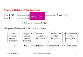
Tritium recovery systemsKyushyu Univ.: S.Fukada Permeation leak through the recovery system is a crucial problem • Small amount of Flibe or He gas flow in the double tube are good as permeation barrier to reduce < 10Ci/day. • The most serious problem is permeation leak of ~34 kCi/day through the heat exchanger to the He loop
Energy conversion systemsfor Flibe in/out temperature of 450˚C and 550˚CKyushyu Univ.: A.Shimizu Three-stage compression-expansion He-GT system was newly proposed • max ~ 37% for compression ratio of 1.5, • However, max decreases rapidly with the increase of pressure drop. • Therefore the layout of energy conversion system is a key design issue. Thermal efficiency Relative pressure drop
innovative free surface wall* designKyoto Univ.: T.Kunugi*KSF wall (Kunugi-Sagara type Free surface wall) • Micro grooves are made on the first wall to use capillary force to withstand the gravity force • Numerical simulation has explored the formation of a pair of symmetrical spiral flow, • which enhances heat transfer efficiency about one order.
TNT loop ~ 0.1m3, < 600°C Thermofluid R&D activitiesTohoku Univ.: H.Hashizumefor enhancing heat-transfer in such high Prandtl-number fluid as Flibe • “TNT loop” (Tohoku-NIFS Thermofluid loop) has been operated using HTS (Heat Transfer Salt, Tm= 142°C) • Results are converted into Flibe case at the same Pr=28.5 (Tin=200oC for HTS and 536oC for Flibe) • Same performance as turbulent flow is obtained at one order lower flow rate. • This is a big advantage for MHD effects and the pumping power.
Bird’s eye view of TNT loop Air Cooler Control Room Upper Tank Test Section Main Pump Dump Tank
Self-cooled Be-free Li/V blanketNIFS : T.Tanaka, T.Murogabased on R&D progress on in-situ MHD coatings and high purity V fabrication • Simple models are evaluated as alternatives for FFHR2 blanket.. • Balance of TBR and the shielding performance is examined, because shielding is poor w/o Be. • TBR of Li/V is higher than 1.3 at about 50 cm with an acceptable shielding efficiency for super-conducting magnets.
10m 5 mm 10-25 m 100 mm Insulator Channel wall (V) Inner layer(V) B field Modeling to Evaluate MHD pressure drop is established for self-cooled lithium blanket.Tohoku Univ. : H.Hashizume • Three-layered wall is proposed, where the inner thin metal layer protects permeation of lithium into the crack of coated layer • Extremely good agreement between FEM and theory has been obtained • The performance required to the insulator is evaluated to be
ITER-TBM Frame? Resouce? Present R & D activities on Flibe blanket in Japan Presented by A.Sagara(NIFS) , Feb.’04 FY1993 1997 2001 2004 2007 2015 • Helical reactor FFHR design • with R&D $ • R&D/LHD • TNT loop • Ultrahigh HT $ • JUPITER-II $
Japan Flibe/RAF blanket, Li/V blanket, SB-He/SiC Blanket R&D in Japan-US joint project JUPITER-II(FY’01~’06) INEEL 1-1-A: FLiBe Handling/Tritium.Chemistry 1-1-B: FLiBe Thermofluid Flow Simulation 2-2 : SiC System Thermomechanics 3-1: Design-based Integration Modeling 3-2: Materials Systems Modeling UCLA ORNL ANL (2001) 1-2-B: V Alloy Capsule Irradiation 2-1 : SiC Fundamental Issues, Fabrication, and Materials Supply 2-3 : SiC Capsule Irradiation 1-2-A: Coatings for MHD Reduction http://jupiter2.iae.kyoto-u.ac.jp/index-j.html
Selection of lower • To reduce mag. foop force • To expand blanket space 1993 FFHR-1 (l=3, m=18 ) • R=20, Bt=12T, b=0.7% • 1995 FFHR-2 (l=2, m=10 ) • R=10, Bt=10T, b=1.8% =tan LHD-type D-T Reactor FFHR Many advantages : • current-less • Steady state • no current drive power • Intrinsic divertor LHD operation: 1998 ~
However, direction of compact design has engineering issues • Insufficient tritium breeding ratio (TBR) • Insufficient nuclear shielding for superconducting (SC) magnets, • Replacement of blanket due to high neutron wall loading • Narrowed maintenance ports due to the support structure for high magnetic field Blanket space limitation Replacement difficulty
New design approach is proposed to overcome all these issues • Introducing a long–life & thicker breeder blanket • Increasing the reactor size with decreasing the magnetic field • Improving the coils-support structure Blanket space Replacement
operation Be First wall First wall Carbon Carbon Breeder Breeder Fast neutron Fast neutron this work TBR ISSEC : by Kulchinski, ‘75 STB & optimization Proposal and Optimization of STB (Spectral-shifter and Tritium breeder Blanket) • Lifetime of Flibe/RAFS liquid blanket in FFHR ~ 15MWa/m2 • Neutron wall loading • in FFHR2 in 30 years • 1.5MW/m2 x 30y = 45MWa/m2 factor 3
Tritium breeding Shielding efficiency
Results and Key R&D Issues Results : • Fast neutron flux at the first wall is factor 3 reduced. • Local TBR > 1.2 is possible. • Fast neutron fluence to SC is reduced to 5x10²²n/m2 (Tc/Tco>90% in 30y) • Surface temperature < 2000°C(~mPa of C) is possible Required conditions : • Neutron wall loading < 1.5MW/m2 • Blanket thickness > 1100 mm • for C-Be-C tiles > 100W/mK • Super-G sheet for tiles joint > 6kW/m2K • Heat removal by Flibe > 1MW/m2 Design parameter Key R&D issues : • Impurity shielding in edge plasma • Neutron irradiation effects on tiles at high temperature • Heat transfer enhancement in Flibe flow
Improved design parameters Improved input Required Blanket space Required Wall loading
Self-ignition access in FFHR2m1 Zero-dimensional analysis • H ISS95 = 1.2 x 1.6 • t* / E = 3 ( < 7) • parabolic profiles • ne< 1.5 x Sudo limit • heating efficiency = 0.9 Already achieved in LHD O.Mitarai et al., Fusion Eng. Design 70 (‘04) 247.
Self-ignition access in FFHR2m2 Zero-dimensional analysis • H ISS95 = 1.1 x 1.6 • t* / E = 3 ( < 7 ) • parabolic profiles • ne< 1.5 x Sudo limit • heating efficiency = 0.9 Already achieved in LHD O.Mitarai et al., Fusion Eng. Design 70 (‘04) 247.
Improved Design of Coil-supporting Structure (1/2) • Cylindrical supporting structure under reduced magnetic force, which facilitates expansion of the maintenance ports. • Helical coils supported at inner, outer and bottom only. • W/H = 2 & H/ac determined by • Bmax ~ 13 T for such as Nb3Sn or Nb3Al. • Then J=25~35A/mm2 • Poloidal coils layout as for stored magnetic energy and stray field design point
Improved Design of Coil-supporting Structure (2/2) Coil current (MA) HC 43.257 OV -21.725 IV -22.100 FFHR2m1 • The maximum stress can be reduced less than 1000 MPa (<1.5Sm) • This value is allowable for strengthened stainless steel. Electromagnetic forces on a helical coil of FFHR2m1. on poloidal coils
Replacement of In-Vessel Components (1/2) • Large size maintenance ports at top, bottom, outer and inner sides. • The vacuum boundary located just inside of the helical coils and supporting structure. • Blanket units supported on the permanent shielding structures, which are mainly supported at their helical bottom position.
Replacement of In-Vessel Components (2/2) Proposal of the “Screw coaster” concept to replace STB armor tiles • Replacement of bolted tiles during the planned inspection period. • Using the merit of helical structure, where the normal cross section of blanket is constant. • Toroidal effects can be adjusted with flexible actuators.
favail = 0.85 - favail *1.4 w *tm / Wtb Cost EstimationUsing PEC code developed in NIFS.Calibrated with ARIES-AT, ARIES-SPPS, resulting in good agreement within 5 %. (T.J.Dolan,K.Yamazaki, A.Sagara, in press in Fusion Science & Tech.) • COE’s for FFHR2, FFHR2m1 and FFHR2m2 decreases with increasing the reactor size,because the fusion output increases in ~ R2, while the weight of coil supporting structure increases in~ R 0.4 ( not ~R3). • When the blanket lifetime ~ 30y, the COE decreases ~20%due to higher availability and lower cost for replacement.
Conclusions Design studies on FFHR have focused on new design approaches to solve the key engineering issues of blanket space limitation and replacement difficulty. (1) The combination of improved support structure and long–life breeder blanket STB is quite successful. (2) The “screw coaster” concept is advantageous in heliotron reactors to replace in-vessel components. (3) The COE can be largely reduced by those improved designs. (4) The key R&D issues to develop the STB concept are elucidated.