Understanding Logic Gates and Decision-Making in Electronic Systems
This guide explores the fundamental concepts of logic and decision-making in electronic systems, emphasizing the role of logic gates in processing inputs. It details the construction of truth tables for various gates such as NAND and NOR and covers the integration of logic gates into circuits using Boolean expressions. The importance of combinational logic systems is also highlighted, along with practical assignments that include designing truth tables and logic diagrams, aimed at enhancing understanding of electronic logic systems.

Understanding Logic Gates and Decision-Making in Electronic Systems
E N D
Presentation Transcript
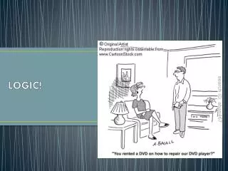
Logic Making decisions Although it may not always seem like it, electronics and electronic systems are very logical in the way that they work. In the simplest form, if you want a light to come on, then you press a switch. Of course, it gets more complicated than that. Most technological systems involve making more complicated decisions: for example, sorting out bottles into different sizes, deciding whether a room has a burglar in it or not, or knowing when to turn a central heating system on or off.
Logic Gates Logic gates are very useful in dealing with and processing a combination of different inputs. This switching logic can be applied to electrical switches and sensors, pneumatic valves or hydraulic systems. Switching logic uses logic gates to perform decisions. In previous work you have already seen NOT, AND and OR logic gates. Task: Draw a Truth Table for each of the Logic Gates shown.
Integrated Circuits Although logic gates have electronic symbols, they are not discrete components: they are contained in integrated circuits. A typical example is the TTL7400 IC shown below. Your data book is useful tool to help identify Ics. Have a look now!
Nand Logic Gate Construct the circuit shown using Croc Clips and then complete the Truth Table.
NOR Logic Gate Construct the circuit shown using Croc Clips and then complete the Truth Table.
Boolean Expressions Each logic gate has a corresponding Boolean mathematical formula or expression. The use of these expressions saves us having to draw symbol diagrams over and over again. The name Boolean is taken from an English mathematician, George Boole, who founded symbolic logic in the nineteenth century
Using Nand Gates NAND gate technology can be used to build other logic gates using NAND gates only. (The same thing can be achieved using NOR gates, but NAND gate chips are more common.) What benefit do you think there might be in using jut 1 type of logic gate?
Using Nand Gates You only have to stock one type of chip instead of a large range. People only have to be familiar with the characteristics of this one chip. Very often significant simplification of complex circuits is possible, thus reducing the number of chips required.
Pupil Assignment Redraw the following logic systems replacing the logic gates with combinations of NAND logic gates. Use the equivalents shown on the previous slide.
Building up a Truth Table Decimal equivalent 4 2 1 Say we have 3 inputs to a logic system, using powers of 2 we can calculate the number of possible combinations of input to the circuit as follows, No. of combinations = 23 = 8
Combinational Logic So far in this unit of work we have only looked at simple logic systems on their own. In reality, most logic systems use a combination of different types of logic gates in one system. This type of logic control is known as combinational logic. Questions 1. What is this system designed for? 2. What is the purpose of the AND gate? 3. Why is the inverter (NOT gate) included?
Worked Example Draw up the truth table and fill up to point D
Worked Example Draw up the results for point Z. (This is the output from the OR gate, being fed by output D and input C only.)
Pupil Assignment Draw up a truth table for each of the following logic systems.
Pupil Assignment Draw up a truth table for each of the following logic systems.
NAND and NOR gate TT Note the extra columns for the inversions of the NAND & NOR
Pupil Assignment Draw up a truth table for each of the following logic systems.
Logic Diagrams from T. Tables The truth table below shows two inputs, A and B, and one output, Z. The output Z is at logic 1 in the third row down, and we can see that for this to happen A must be at logic 1 and B must be at logic 0. In other words
Worked Example Copy down the truth table into your workbook. Your teacher will work through the solution with you.
Pupil Assignments Copy down the truth table, then draw the logic diagrams for each of the following truth tables.
Logic Diagrams from a Spec Worked example A burglar alarm system is to sound if a master switch is on and either a light beam is broken or a pressure pad is stood on. Draw a logic diagram and a truth table for this system. Read the specification carefully. You should notice that it has three inputs. These are: a master switch (M) a light sensor (L), and a pressure pad (P). It has one output, an alarm bell (B). The bell should go to logic 1 if the master switch is at 1 and either the light beam goes to logic 0 or the pressure pad goes to logic 1. This can be written in Boolean as:
Logic Diagrams from a Spec The truth table for this system is shown below. Again, all you have to do is read the specification carefully and then read across each row, one at a time, and decide whether the bell should be ringing or not.
Pupil Problems • A house doorbell is to ring if a push button at the front door, a push button at the back door or both buttons are operated. Draw a logic diagram and write a Boolean equation. • A lift motor is to start only when, by closing, the door has actuated a switch and a passenger has pressed a button. Prepare a truth table, a logic diagram and a Boolean equation for this system. • The driver of a dustcart is to be able to operate the loading claw by pressing a button, but only when the senior loader at the rear of the cart has pressed a button to give the ‘all clear’. Draw a logic diagram and write a Boolean equation for this system. • An automatic central heating system is to heat the radiators (R) if the mains switch (M) is on, the timing control switch (T) is closed and the override button (O) is not selected. Draw a logic diagram, truth table and Boolean statement for this system.
Pupil Problems • A drill is to operate if an isolator is closed, a guard is in place (closing a micro switch), either ‘HI’ or ‘LOW’ speed is selected and a foot pedal is operated. Draw a suitable logic diagram for this system. Draw up a truth table. • A large hall has three temperature sensors. A logic system is to operate the radiator when any two of the temperature sensors fall below a preset level. Draw up a truth table for this system and draw a logic diagram. • A burglar alarm will operate if the mains switch is on and either an electronic beam is broken, a pressure pad is stood on or a window is opened. Draw a logic diagram for this system.
Logic Gate Integrated Circuits Integrated circuits consist of plastic cases filled with electronic circuitry. There are many resistors, transistors and other components packed into the chips. There are literally thousands of ICs on the market, all designed to do different jobs – logic gates, amplifiers, timers, etc
TTL Integrated Circuits • There are two main types of Integrated Circuit, (IC) • TTL (Transistor - Transistor Logic) TTL Advantages - Very fast switching speed. - Unused pins can be left to float, unattached. TTL Disadvantages - Low fan out (number of subsequent gates it can drive. - Requires a stabilised voltage supply, (5V).
CMOS Integrated Circuits • CMOS (Complementary Metal Oxide Semiconductor) CMOS Advantages - High fan out (number of subsequent gates it can drive. - Works on a wide supply voltage, (5 – 15V) CMOS Disadvantages - Slower response / switching time. - Unused pins must be tied to supply rails.
TTL Integrated Circuits In our work we will only consider TTL. However, you need to remember the advantages / disadvantages of each type. All TTL chips have a four-digit code number, which always starts with 74. For example, a 7400 is a quad two-input NAND chip. Although the chip contains complex circuitry, the internal wiring can be shown as simple logic circuits with the inputs and outputs of each logic gate shown. This is called a pin-out diagram. Your Data book lists the most common IC’s Pin 14 is connected to the 5-volt stable supply and pin 7 to 0 volts
Prototype Board Prototype board is used to build prototype circuits. It is much better to test a circuit on prototype board before mass producing the circuit. Why do you think this might be?
Pin Out Diagrams ICs are impossible to use without the manufacturer’s data sheets to show what facilities are available on the chip and how the pins are to be connected. These data sheets contain pin-out diagrams. A pin-out diagram is a graphical layout of the chip and its contents.
Pin Out Diagrams The description of each pin-out diagram gives details of the chip. For example, a ‘dual four-input NOR’ means the chip has two (dual) NOR gates on it, each having four inputs. A ‘quad two-input AND’ means the chip has four AND gates, each gate having two inputs.
Pin-out and wiring diagrams Your teacher will show you how to convert this logic circuit into a pin out diagram
Pupil Assignment Draw a pin out diagram for each of the following combinational logic circuits.
Pupil Assignment • Copy each of the shown logic diagrams into your workbook. • Construct a truth table for each. • Draw a pin out diagram for each. • Simulate using Croc Clips to confirm your truth table.
Test Equipment When trying to establish logic levels within a complex system or to monitor a logic output without using an LED, we use a digital logic probe. The logic probe is powered from the same supply as the logic circuit being tested and the needle point is pushed against the various pins on the IC to test their logic level. Normally the logic probe gives out a high-pitched sound and a red LED lights if the pin being tested is at logic 1. If the point tested is at logic 0, a low-pitched sound is emitted and a green LED lights. Your teacher will allow you to test a simple circuit using the logic probe.