Accelerator Systems Overview
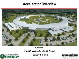
Accelerator Systems Overview. F. Willeke 4 th Accelerator Scientific Advisory Committee Meeting July 17-18, 2008. Overview. Introduction Lattice and Accelerator Physics Magnet Design and Prototype Production Support systems and Alignment Instrumentation RF Controls.

Accelerator Systems Overview
E N D
Presentation Transcript
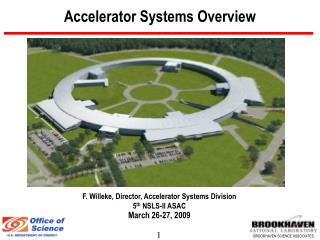
Accelerator Systems Overview F. Willeke 4th Accelerator Scientific Advisory Committee Meeting July 17-18, 2008
Overview • Introduction • Lattice and Accelerator Physics • Magnet Design and Prototype Production • Support systems and Alignment • Instrumentation • RF • Controls
NSLS-II Accelerator Design Goals Beam Energy: Quasi constant, high Beam Current: Small Radiation Source Size: - horizontal Beam Emittance: - vertical Beam Emittance: Moderate Beam Energy Spread: High Orbital Stability: Large Space for Insertion Devices: E = 3 GeV I = 500 mA,DI/ I = 1% ex= 0.6 nm ey = ~ 8 pm (diffraction limited @12keV) DE/ E = 0.1% (RMS) Dz, Dz’ = 10% ·sz,sz’ LID = 226 m (28.5%), with bending magnet sources included space for at least 58 beam lines
… Achieved by the following design featuresWBS 1.03 • Large circumference C = 792 m • Large number of achromats N = 30 • Robust double bend achromatic optics eb= 2nm @ 2 x (theoretical minimum) • Low bend field B = 0.4 T low radiation loss U0=286kV • Damping wigglers for small emittance e = e0×U0 / ( U0+Uw ) • Top-Off Injection • On-Energy Injection
NSLS-II Accelerator Overview Storage Ring: 30 DBA Cells Large storage ringC = 792m with 30 double bend achromats 30 straight sections - 15 long (9.3m) - 15 short (6.6m) Straight Including: 1 injection (long) straight 2 RF (long) straights with 2 sc single cell 500 MHz cavities 1.5 GHz passive s.c cavity . for bunch lengthening 3 (baseline)- 8(full scope) damping wiggler straights, 2x3.5m 1.8T Damping Wigglers each Injector: Compact booster synchrotron fed by a 200MeV S-band linac
Response to Last MAC Variable Gap Wiggler: Response: The horizontal space in the tunnel is considered not sufficient to provide a fully variable gap damping wiggler. Other means are explored: - Dedicated tuning wiggler - Alternative means of beam control Alternative Wiggler Designs Response:The wiggler design is based on straight magnet Few Longer Straights Response: We are working towards a decision in Spring 09 whether to go with a fully symmetric lattice or with a reduced symmetry lattice, first results are available already Limited Dynamic Aperture with IDs Response: This is a focus of the FY08/09 accelerator physics activities
General Status • NSLS-II Accelerator systems made steady progress since the last ASAC meeting. • FY08 started with a 3 Mio $ funding deferral of PED funds into FY09 • Parts of the R&D program (permanent magnet laboratory development and LINAC frontend studies) delayed • R&D program has concentrated on areas where designs need to be finished: magnets and support structure, alignment and stability • Design has advanced in areas where production needs to start in 2009 in order to be able to start installation in 2011: Magnets, support systems, vacuum system, any area which interfaces with the building and conventional system: electrical and mechanical utilities, cryogenic system, RF • The important next goal is to get CD-3 approval in order to be able to start constructing the ring building
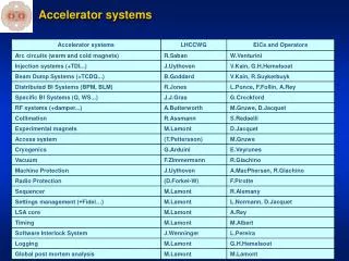
Interface to CF • Layout of electrical systems in building performed and AC distribution system defined • Distribution of Electronic Racks on Tunnel Mezzanine laid out, design and location of cable conduits performed and defined • Detailed NSLS-II cable plans for all subsystems produced • Chilled and process water system architecture revised • Result is a more centralized system with less components, less space requirements and more maintenance friendliness • Interface of RF and CF defined • Interface Injector and CF defined ACCELERATOR – CIVIL CONSTRUCTION INTERFACE WELL DEFINED BY NOW
Accelerator Physics • Lattice design stable since January • Orbit correction scheme revised, dynamic orbit correction schemes developed • Decker distortions and canting of wigglers integrated in lattice • Feasibility of extra-long straight evaluated • Dynamic aperture analysis is continuing • Field quality of the magnet system defined based on thorough analysis of the nonlinear dynamics performed • Systematic impedance assessment of components of the vacuum system in progress • Integration of damping wigglers: work in progress
Dynamic Aperture with Multipole Errors DA small @ -3% Dp/p Systematically studied, well understood Introduction of high precision Q+S magnets in center of achromat
Top Off Safety Study Goal: Need to understand what limiting apertures and additional measures have to be Started to model accelerator components with/without magnetic field defect Collaborations with LBL, SLAC Sweeper magnet Safety Shutter Fixed Mask 13.54mm, half aperture 8.84mm, half aperture MIDPOINT OF LONG STRAIGHT 37 112 38 75 23 Stick Absorber 38 LBL top off back tracking code
Progress with NSLS-II Magnet Systems • Reference Design of NSLS-II quadrupole and sextupole magnets refined and completed TIGHT FIELD TOLERANCE SPECIFICATIONS MET • Contracts for 9 prototype dipoles, quadrupole and sextupole, magnets awarded to three vendors • Short Prototype Dipole magnet (35mm gap, 1m long) received, measurement program started • Tests on dynamic dipole corrector magnets performed, design improved based on tests • Study of 10-pole correctors performed • Cost estimate of magnet system updated based on 2008, vendor quotes (eight interested vendors) • Girders redesigned for 1.2m beam height • Vibration tests performed on test girder • Alignment procedure refined and demonstrated
Magnet Types in a Cell Correctors Six types of quadrupoles Three types of sextupoles Two types of dipoles 2 types of correctors Wide Quadrupoles & Sextupoles to accommodate X-ray transport. Regular Quadrupoles &Sextupoles Dipoles
Support system Corrector Magnet Sextupole Magnet Quadrupole Magnet Vacuum Chamber Girder Floor Plate Re-designed for 1.2m beam height Vibration studies Reproducibility after thermal and mechanical cycling tested
Progress of Vacuum System • Vacuum chamber design well advanced, prototype chamber in production • Various prototype chambers from extruded Aluminum received, two vendors qualified to meet NSLS-II requirements • Machining on short test chambers needed for welding tests ( performed at ANL) • Shielded bellow designs developed, impedance models generated and evaluated • Chamber heating and conditioning tests underway, kapton imbedded heater tests successful, alternative method (direct electrical heating) in progress, need of pressurized hot water eliminated • NEG-support structure developed • Integration of BPM in progress • Ozone Cleaning System procured and being assembled
Injector • Preliminary Design for Turn Key System carried out • Beam optics flexibility and dynamic aperture study carried out • Discussed the design with two potential vendors • Contacts made to 3rd interested vendor for booster turn-key procurement • Interface between injector and conventional facilities defined • Beam Transport Line design carried out and iterated with layout of the building and refined (0.2-3) GeV C= 158m; 1Hz Booster synchrotron 200MeV S-band Linac 15 nC/s ALL THE INTERFACES BETWEEN CIVIL CONSTRUCTION AND INJECTOR WELL DEFINED
Lattice Booster Dynamic aperture Dipole physical aperture Structure Dynamic Aperture
Technical Progress: Instrumentation • BPM System Emphasized: • R&D on BPM stability and noise suppression • IID BPM: Stand with high stability and small thermal expansion • BPM Button Optimization for maximum resolution • Button Heating under study • Study of electronics stability
RF Most important task for RF system was to clarify any interface with the construction of the buildings RF system still based on the CESR-B type single cell 500 MHz super conducting cavity LLRF system is in the centre of 2008 technical development • FPGA based control module (cavity tuning, RF phase loop and amplitude loops, ) has been designed PC board has been fabricated, final assembly of the controller is in progress • Extensive Matlab modeling in progress to optimize the FPGA based tuning and control algorithm needed to satisfy high demands on RF phase stability of 0.5degree driven by external IR beam requirements • Value engineering on main RF power source underway, goal is to make a decision on klystrons versus combined IOT system by September 09
Controller status • Prototype board being assembled this week • Will test ADC and DAC interfaces, FPGA firmware and allow measurements of noise floor • MatLAB based system model will directly code FPGA control loops; Matlab modeling is in development • Designed to meet SR requirements, but will be used for booster, harmonic cavities by changing firmware, saving on hardware design, controls hardware and GUI interfaces • Includes a redundant serial communications link specified by controls group - LBL collaboration (uses ethernet hardware without the protocol)
PS System • Design of power supplies for the main dipole and quadrupole, sextupole, and corrector magnet in progress • Prototyping of Fast Corrector Supply • Equipment Enclosures Prototypes being tested • Detailed layout of cable system including cable conduits / penetrations from mezzanine into tunnel, cable trays, AC distribution Fast Corrector Prototype Open loop performance fast corrector Ongoing tests with corrector magnet prototype
Equipment Enclosure Designs • Air Cooled Racks with chilled water heat exchangers Prototype built and tested
Equipment Enclosures Prototyping and Testing
Control System Efforts concentrated on three areas: • Controls Architecture Development development is the embedded device controller - standard EPICS installed and control system studio a collaborative set of operator applications being developed at DESY and SNS. • Relational Database Development Development/formatting of of configuration tools, scripting tools, web-based reports and machine files • High Level Application Platform online model running tracy 2 is operational with a lattice derived from an elegant desk As it runs under EPICS all of the channel access clients work on it including the XAL tools and the matlab middle layer toolkit and SDDS for that matter. open-source protocol (DDS)is examined whether suitable for the high level application architecture.
Control System Architecture Status Operator stations: Displays, Archiving, Alarm Management, Strip charts, Save/Restore Utility Events/ / Timing Data Shared Memory Ethernet – EPICS Channel Access Protocol CPU CPU EVR CEL L EVR CEL L EVG CEL L CPU Standard EPICS Tools are installed Control System Studio is being evaluated Shared Memory Network Prototype Power Supply Device Interface LLRF Device Interface Beam Line Motion Control Prototype BPM IOCs PS IOCs Timing Master BPM PS Fast Equipment Protection Signal BPM PS BPM PS BPM PS BPM BPM
Database Status Web Based Reports Configuration Tools Component Type Component Lattice EPICS Database Name Mapping Wiring Component Type Component Lattice EPICS Database Name Mapping Wiring Components Lattice EPICS Database Name Mapping Wiring Scripts Files for control Component Type Component Lattice EPICS Database Lattice EPICS Database Name Mapping Complete Complete FY 08 Complete FY 09 Support expands over project for physics applications and maintenance support
High Level Applications – Client/Sever The online simulation is running XAL is installed and running for many operator functions EPICS tools can look at simulation – including archiver The NSLS II lattice is loaded as EPICS Channels from script DDS protocol is being evaluated for use as client/server layer Lattice EPICS Tools ) XAL Tools (not beam based Control) Matlab Applications EPICS Client/Server I/O Controller – Tracy 2 Simulation NSLS 2 lattice running
Accelerator Systems Leads L. Dalesio L. Doom G. Ganetis C.H..Hseuh E. Johnson S. Krinsky Controls Design Room Electrical Sys. Vacuum Stor. Ring Coord. Acc. Physics O. Singh J. Rose T. Shaftan S. Sharma T. Tanabe F. Willeke Instrumentation RF Injector Coord. Mech. Syst. Insertion Dev. Div.Dir.
STAFF Accelerator Systems Division Work Force: 56 Staff + ~20 MOU + ~ 5 FTE Temp 80 total workforce @ 60FTE for FY08 (so far) FY 2008 hires: 17 new scientists and engineers hired Acc.Physics Group Leader appointed, Injector and Storage Ring Coordinators identified
Accelerator Systems Data Organization • Systematic Collection of Information • ASD Interface meetings and supporting documentation • RSI Documents • E-discussions (where meetings are not practical) • Develop standards and conventions • Storage Ring Naming Convention • Nomenclature RSI • Technical Change Request procedure • Publication of key references and data • Global parameters (includes ASD, CFD and XFD information) • System specific parameters (eg lattice definition) • Interface properties (eg shielding penetrations)
Value Engineering and Technical Change Control Formal Procedure of Value Engineering and Controlled Technical Change • developed, • implemented, and • in use NSLS-II CCB
Assembly and Workspace Management Production, Acceptance Test, Assembly and Installation plan generated, NSLS-II Acc. Space requirements updated
Cost Estimate with FY08 $ 3M Budget Deferral for ACCELERATOR PED Implemented
Accelerator Systems Schedule (as shown at last meeting) • Booster on the critical path • Reason: • Injector Turn-key procurements delayed to preserve option for alternative vendor development of change of procurement plan as part of the injector risk mitigation strategy • It also helps to match the time phased cost estimate with the funding profile • After May 2013: Accelerator and ID commissioning
Summary • Overall Good technical progress with NSLS-II accelerator systems design • The interfaces with the ring building have been clarified in a detailed and comprehensive manner • Progress in critical R&D activities: alignment, magnet prototyping • Organizational procedures developed and organization strengthened • Staffing Plan is in general on track • Accelerator Systems will be ready for CD-3