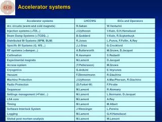
Accelerator Systems Overview
390 likes | 524 Views
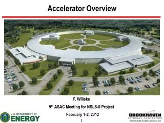
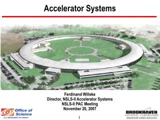
Accelerator Systems Overview. F. Willeke, ASD Director 6 th ASAC October 22-23, 2009. Outline. Comments on Charge Responses to last ASAC Meeting Conclusion of the R&D Program Development in Overall Accelerator Design Technical Progress of Subsystems Cost and Schedule Performance

Accelerator Systems Overview
E N D
Presentation Transcript
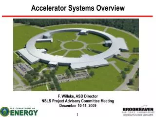
Accelerator Systems Overview F. Willeke, ASD Director 6th ASAC October 22-23, 2009
Outline • Comments on Charge • Responses to last ASAC Meeting • Conclusion of the R&D Program • Development in Overall Accelerator Design • Technical Progress of Subsystems • Cost and Schedule Performance • Organizational Issues • Outlook
Charge • Review AS recent progress & near-term plans: technical, cost, & schedule performance overview presentation • Review the plans for BPM system, comment on in-house development regarding technical performance, cost, and schedule dedicated presentation • Review the overall machine protection system and the integration of personal protection system, beam containment and top-off safety measures 3 dedicated presentations • Comment on the Injection systems including the plan for the pulsed magnet facility and the procurement strategy for the booster Injector presentation • Review and comment on the NSLS-II power supply systems dedicated presentation • Review the plans for production, assembly, and installation of accelerator systems dedicated presentation • Review the plans for start-up, test, and commissioning of accelerator systems Dedicated presentation
Response to the Committee’s Recommendations Project acknowledges importance of comment, BB monitor calibration planned to be used, achievable precision 2008 tech note Workshop held, positive feedback This is being done, but not systematically, so far given our present solution, overall tune footprint shrinks with positive xx Prototype would be too costly, not in budget, vertical cold tests are planned, no vendor decision yet comment is acknowledged & taken into account in the ongoing design considerations Aggressive staffing plan pursued, resources from other labs used (Al Chamber welding, DW, controls) Magnet procurement split into 5 packages, sextupole and quadrupole packages split into 2 similar sub-packages • Achievable precision of BPM offset by BBA Introduce realistic errors into the orbit and optics correction model! • In-depth workshop of the storage ring lattice and tracking results in the near future • Investigate the performance of the Storage Ring lattice at higher positive values of vertical chromaticity, which are generally required to control instabilities! • The Project should plan on building and testing a (500MHz) superconducting cavity prototype, especially if the contract goes to a company that has no experience • Make an effort to decrease R/Q of the passive cavity. • Keep focus on rapid staff-up. Look for resources at other labs. • Give serious consideration to parallel awards and “easy” escape clauses in contracts for magnets, to facilitate a shift of scope from one vendor (who might not be performing satisfactorily) to another
Nonlinear Dynamics Review Methods and procedures endorsed 3rd chromatic knob recommended No preference of how to implement
Status Overview Accelerator Systems Design is coming to an end: - Accelerator Lattice is stable now, do not expect significant changes - Design of Injector, SR Magnets, Girder, Vacuum Chambers, Utilities completed or far advanced & Prototypes built and tested successfully -Outstanding Designs: Power Supplies, Insertion Devices, Instrumentation Safety Systems, RF cavities (modifications to meet code) Procurement of major systems started: SR Magnets orders have been placed LINAC RFP published Vacuum Chambers and components production started Booster RFP in preparation Many procurements such components for accelerator production and test facilities in progress
Accelerator Physics • Dynamic Aperture : Magnetic field specifications updated • Chromatic corrections improved 23 chromatic sextupole families decision made • Integration of Damping wigglers improved acceptable DA with 3 DW and up to 10 IVUs, work on EPU accommodation started • Work on Beam confinement including planned experiments, top-off safety study continued • Revision of fast orbit correction: separated function scheme reduces performance risk • Impedance calculations pursued, collaborating with instrumentation and vacuum on suppression of rogue mode, calculations and measurements (review held in September) • Transv Damper conceptual design: filtering ( Button BPM, locations, detector layout, Digital filter layout 9-tapFIR, strip-line kicker)
SM1L SM2 SM1R 0.67 0.2 QM1 QM2 QM2 QM1 Introduction of a Third Chromatic Knob Center of Long Straight Center of Short Straight Center of Long Straight • Symmetry in lattice: • Reflection symmetry about the center • of the straights • Reflection symmetry and translation symmetry between super-periods • Functions of the sextupoles: • 2 chromatic sextupole families to • correct the linear chromaticity; • 7 geometric sextupoles to compensate • the nonlinearity • One more chromatic sextupole to • correct the nonlinear chromatic • effects.
Dynamic Aperture with Insertion Devices Frequency Map Simulation (RADIA kick map used) basis lattice with well compensated chromaticity and tune shifts add IVU and imperfections Add DW Effect of DW is mainly linear Optics Distortion Can be well integrated (requires 3-f symmetric installation) Add EPU’s
Injector System • The RFP of the 200MeV s-Band Linac will be published end of October; there are 4 strong vendors • Booster will be semi turnkey, vendor responsible for overall performance, some subsystems (controls interfaces, BPM electronics, installation labor contributed by BNL) • Transfer line design matured • Transfer Line magnet design in progress • Pulsed Magnets Workshop in August Pulsed Sextupole Injection Scheme abandoned, baseline: 4kicker-bump • Pulsed magnet laboratory installed
Storage Magnet Systems Orders have been placed for the industrial production of NSLS-II Storage Ring Magnets The 240 68mm aperture quadrupole magnets in 6 variants will be produced by Everson/Tesla and BINP, orders placed Sept 23 The 68 mm sextupole magnets will be produced by IHEP and Danfysik, Orders placed October 16 The 60 large aperture quadrupoles and the 30 large aperture sextupoles will be produced by Buckley, orders placed Oct. The vendor for the 54 35mm aperture and the 6 90mm dipoles has been selected. The 180 100mm and 156mm hor./vert. correctors will be produced by Everson Tesla.
Girder, Supports and Integration • Girder R&D and Girder Design Completed Manufacturing Drawings being completed • The precision alignment procedure is well defined by having tested each step in the procedure • The R&D and the design of the girder system is complete, all the critical issues have been addressed and solved. Ultimate test: After transport, all magnets within 5mm aligned • Environmental Room equipped and functional • The girder integration procedure re-planned: only one environmental room necessary, final magnet adjustment performed manually; - optimizes procedure - this will save costs - helps to compensate the enhanced labor needed in setting up the production facility and performing R&D dedicated presentation Fully Functional and Equipped Environmental Room (DT < 0.1 C ) for 30 mm Precision Alignment
Final Demonstration of Feasibility of 30mm Magnet-to-Magnet Alignment June 2009
Mechanical Systems, Front-Ends • Front end design 80% complete • Outside-Vacuum prototype of safety shutter built, cycle-tested successfully • Compressed gas system redesigned and based on compressed air • DI water systems (5 x CU; 5 x AL, RF, Linac, Booster, Cryo-Compressors) detailed system design, component layout, service building equipment room detailed design with 3-D layouts
Vacuum Systems Prototype chamber invar support on girder • Vacuum Production Facilities: Clean-room for assembly prepared, vacuum conditioning lab is now fully equipped and tested, vacuum cleaning and measurement lab started to operate (late) , brazing oven installed, chemical cleaning procurement delayed • Vacuum Chamber prototype extrusions successful, orders for production of MP extrusions place, dipoles will follow soon, dipole chamber bending under control, but is considerable effort; contracts for prototype welding and machining in place; vacuum chamber bake-out iterated and improved, Bi-metal flange in production • Collaboration with APS in place for Production Chamber Welding • NEG Pump Design tested, support system iterated and improved, Rogue mode shielding integrated • Novel Design for Shielded Bellows, 2nd prototype being built • Commercial Ion pump comparative test Dipole chamber bending New Vacuum Chamber Profile Novel Design Shielded Bellow Prototype
RF Systems • Storage Ring SC RF Cavities: Nonlinear Stress Analysis demonstrates compliance with equivalency to pressure vessel code Failure of over-pressured system reproduced benchmarked calculation Procurement documents in preparation reviewed by lab safety committee which confirms adequacy of the procedure • Optimization of Coupling for 500mA • LLRF: 2nd FPGA based prototype build, still basic functionality , under test with Booster 7-cell cavity (tuner loop) • Booster RF: New tuner motors and electronics, adaption of input coupler to co-axial waveguide • RF Power: RF engineer hired, • Cryogenic System: Cryo engineer on board, consultant help to refine valve and pipe dimensions, design being wrapped up resulting in preliminary specification for first iteration with vendor
Instrumentation • BPM System still major activity RF button first article successfully tested, production released Commercially available BPM electronics meets demanding NSLS-II requirements (resolution, stability 0.1mm) Concerns about obsolete electronics and vendor support in-house development seriously considered • Efforts on other diagnostic systems started: Photon BPMs, Fast orbit control, transverse damper system, fast orbit control, optical monitoring, scraper systems, loss monitors New 7mm 2-in-1 RF Button First Articles with Boron Nitride Washers
Electrical Systems Full Power Test of NSLS-II Sealed Air-Cooled Power Supply Rack with prototype PS’s • Main Dipole PS component design and prototype testing well advanced, next step is system integration • MP power supply design meets higher (25 ppm) stability standards easily, order for DCCTs have been placed • New dual corrector power supply in progress • Equipment enclosure design completed and power test on prototype with PS and heaters completed • Detailed cable plans developed, layout of cable trays • Calibration system for PS DCCT developed AC Power Control Module Power Converter DCCT Low noise regulator prototype for Main DP switch-mode supply
NSLS-II Insertion Devices 49 Tanabe’s Presentation
Possible NSLS-II DW Production by APS Damping Wiggler: APS provided a preliminary design, a cost estimate and a schedule. However APS has difficulties with NSLS-II DW specifications. Attractive APS fixed gap NSLS-II DW proposal with horizontally moving in/out beam position
Bldg. 832 3D-Layout ISO-7 Clean Room for Measurement ID Lab Tech Shop RF Lab Pulsed Magnet Lab
Safety Systems Beam Imminent Beacon • Design of SPPS and EPPS systems well advanced, completion end of FY • Successful external reviews of the systems conducted • Engineering prototypes in progress Search In Progress Beacon Emergency Stop Area Secure Search indicator Beam Disabled Search Button Johnson’s Presentation Beam Imminent Siren Single Pentant Siren
Control System High Level Applications -Standard interface for orbit control running using existing beam optics dynamics codes -Data Description Service is deployed as an interface/complement to basic channel access mechanisms. Database: IRMIS API for machine lattice entry and report is running and integrated into the online model environment. Equipment Controls: Preliminary design doc’s for vacuum, power supply, diagnostics, RF, Timing, EPS/PPS Prototype of Controls for Subsystems started Vacuum, beam line, PPS, beam correlated applications, Diagnostics, power supplies, and LLRF Network preliminary design of network hardware system
Registered AS Cost Changes Note: Contingency is owned by Federal Project Director. Numbers are just used as a measure of cost increase!
Schedule CD4
Assessment Trend since October 2008: Cost variance becoming smaller Schedule Variance becoming negative reaching 5.8M$ at the end of FY09 Reasons: Late hires and Missing MOU Labor 36 FTE ( @ 6.0M$ ) • Labor augmentation plan 36FTE to recover since June, too early to see an effect Should start to see improvement within the next 6 month There is one remaining EVMS issue: Controls has worked on activities scheduled to start in FY10 no earned value, self repairing in FY10 There are real delays: Vacuum Chamber 1.5 M$ due to technical issues and procurement or vendor problems and slow progress with the vacuum facility (recovering now) Slow procurement process with many medium size procurements behind schedule Additional procurement support added (Liaison Engineer AS, more buyers)
ASD Shortage of Labor Resources Causes:Late Hires, Resource Leveling, MOU contributing less than planned ASD schedule variance at 4/30 associated with this effect is -4M$ [FTE] [FTE] Difference, Accumulated Difference [FTE]
Mitigation of Schedule Variances Goal: Stop Growth of SV within 3 months recover the schedule within 24months Preliminary Plan in Place to satisfy immediate needs 18FTE, plan to complement by another 18FTE Additional 18 FTE Slow recovery
Accelerator Systems Division Staffing Budgeted Temporary Labor Planned MOU BNL Hired
FY09 AS Hires • FY 09 Staffing • 11 Controls System Experts • 10 Engineers • 7 Physicists • 11 Technicians and Designers • Present staff 103 • Supported 10 FTE MOU
Organization • 23 new key staff hired • Deputy Division Director assigned: E. Johnson • Project Engineer hired: G. Fries • Organization augmented by task forces (FOF, BC) N
Conclusion • Design of Accelerator Systems approaches conclusion: Magnet, Vacuum Chamber design and prototyping ready for production • Accelerator Systems entered the construction phase, major procurements and production have started: SR Magnets, Vacuum Chambers, Production Facilities • Negative Schedule Variance has built up; is mitigated by adding labor to make up for labor resources not available the time work was scheduled, • Focus in the next months will to award construction contracts for magnets, vacuum chambers, LINAC, booster and support systems • Accelerator systems in good shape, no major technical issues, schedule under control