Enhancing Networking Through Parallel Packet Switch Architecture
The research presents an innovative paradigm for high-speed packet switching using Parallel Packet Switches (PPS). By employing multiple slower packet switches operating in parallel, the system aims to achieve optimal performance while ensuring Quality of Service (QoS). Key concepts include inverse multiplexing, work conservation, and effective buffering. The study delves into speedup constraints and provides specific requirements for FIFO and PIFO configurations. This architecture is expected to facilitate a scalable solution in networking, capable of handling diverse demands and reducing memory speed limitations.


Enhancing Networking Through Parallel Packet Switch Architecture
E N D
Presentation Transcript
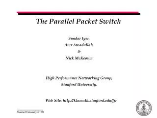
The Parallel Packet Switch Sundar Iyer, Amr Awadallah, & Nick McKeown High Performance Networking Group, Stanford University. Web Site: http://klamath.stanford.edu/fjr
Contents • Motivation • Key Ideas • Speedup, Concentration, Constraints • Mimicking an OQ-Switch • FIFO : A Speedup of 2 suffices • Enabling QoS in a PPS • PIFO: A Speedup of 3 suffices • Motivation for a Distributed Algorithm • Work Conservance: A Speedup of sqrt(k) suffices • Multicasting • FIFO : A Speedup of m +1 suffices • PIFO: A Speedup of 2m +1 suffices • Conclusions
Motivation • To build • a switch with memories running slower than the line rate • an extremely high-speed packet switch • a switch with a highly scaleable architecture • To Support • Quality of Service • To have • Redundancy “I want an ideal switch”
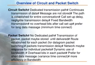
Architecture Alternatives - Refresher Y QoS Support • An Ideal Switch: • The memory runs at lower than line rate speeds • Supports QoS • Is easy to implement Ideal ! PPS Switch ? Output Queued CIOQ Switch Input Queued X 1x Ease of Implementation 2x Nx Z Memory Speeds
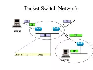
What is a Parallel Packet Switch ? - Refresher A parallel packet-switch (PPS) is comprised of multiple identical lower-speed packet-switches operating independently and in parallel. An incoming stream of packets is spread, packet-by-packet, by a de-multiplexor across the slower packet-switches, then recombined by a multiplexor at the output.
Key Ideas in a Parallel Packet Switch • Key Concept - “Inverse Multiplexing” • Buffering occurs only in the internal switches ! • By choosing a large value of “k”, we would like to arbitrarily • reduce the memory speeds within a switch Can such a switch work “ideally” ? Can it give the advantages of an output queued switch ? What should the multiplexor and de-multiplexor do ? Does not the switch behave well in a trivial manner ?
Definitions - Refresher • Output Queued Switch • A switch in which arriving packets are placed immediately in queues at the output, where they contend with packets destined to the same output waiting their turn to depart. • “We would like to perform as well as an output queued switch” • Mimic (Black Box Model) • Two different switches are said to mimic each other, if under identical inputs, identical packets depart from each switch at the same time • Work Conserving • A system is said to be work-conserving if its outputs never idle unnecessarily. • “If you got something to do, do it now !!”
Ideal Scenario Output-Queued Switch Multiplexor Demultiplexor (R/3) 1 R R (R/3) 1 1 Demultiplexor Multiplexor (R/3) R R Output-Queued Switch 2 2 (R) 2 (R/3) Demultiplexor Multiplexor R R (R/3) 3 3 Output-Queued Switch k =3 Multiplexor Demultiplexor (R/3) R R (R/3 N=4 N=4 Packets destined to output port two
Potential Pitfalls - Concentration “Concentration is when a large number of cells destined to the same output are concentrated on a small fraction of internal layers” Output-Queued Switch multiplexor Demultiplexor (R/3) 1 R R (R/3) 1 1 Demultiplexor multiplexor (R/3) R R (2R/3) Output-Queued Switch 2 2 2 (R/3) Demultiplexor multiplexor R R (R/3) 3 3 Output-Queued Switch k =3 multiplexor Demultiplexor R R (R/3) N=4 N=4 Packets destined to output port two
R R R C3 C1 A R 1 A 1 C1:A, 1 R B R R R 2 B R R 2 C2:A, 2 C2 R R R C R 3 C 3 C3:A, 1 Cells arriving at Cells departing at (c) (d) R R C3 C3 R 1 A C4:B, 2 1 R B R R R 2 B R R 2 R R C R 3 C5 C4 R C C5:B, 2 3 Cells arriving at Cells departing at Can concentration always be avoided ? t=0’ t=0 t=1 t=1’
Link Constraints • Input Link Constraint- An external input port is constrained to send a cell to a specific layer at most once every ceil(k/S) time slots. • This constraint is due to the switch architecture • Each arriving cell must adhere to this constraint • Output Link Constraint • A similar constraint exists for an output port Demultiplexor Demultiplexor After t =4 After t =5 A speedup of 2, with 10 links
AIL and AOL Sets • Available Input Link Set: AIL(i,n), is the set of layers to which external input port i can start sending a cell in time slot n. • This is the set of layers that external input i has not started sending any cells to within the last ceil(k/S) time slots. • AIL(i,n) evolves over time • AIL(i,n) is full when there are no cells destined to an input for ceil(k/S) time slots. • Available Output Link Set:AOL(j,n’), is the set of layers that can send a cell to external output j at time slot n’ in the future. • This is the set of layers that have not started to send a new cell to external output j in the last ceil(k/S) time slots before time slot n’ • AOL(j,n’) evolves over • time & cells to output j • AOL(j,n’) is never full as long as there are cells in the system destined to output j.
Bounding AIL and AOL • Lemma1: AIL(j,n) >= k - ceil(k/S) +1 • Lemma2: AOL(j,n’) >= k - ceil(k/S) +1 k ceil(k/S) -1 Demultiplexor k - ceil(k/S) +1 AIL(i,n) At t =n
Theorems • Theorem1: (Sufficiency) A PPS can exactly mimic an FCFS- OQ Switch if it guarantees that each arriving cell is allocated to a layer l, such that l € AIL(i,n) and l € AOL(j,n’), (i.e. if it meets both the ILC and the OLC) U AIL(i,n) AOL(j,n’) The intersection set • Theorem2: (Sufficiency) A speedup of 2k/(k+2) is sufficient for a PPS to meet both the input and output link constraints for every cell.
Quality of Service: PIFO - Logical View 8 7 6 5 4 3 7 2 6 5 1 8 4 3 2 1 • Logical View • Highest Priority First • 3 priority levels • 3 logical queues • Each logical queue is FIFO
PIFO Queues - Physical View 4 3 7 2 6 5 1 8 8 8 1 8 5 1 8 6 5 1 8 6 5 2 1 • Physical View • Single Queue • The queue is PIFO • The HOL cell is serviced first 8 7 6 5 2 1 8 7 6 5 3 2 1 8 7 6 5 4 3 2 1 Timeline
PIFO in PPS – Candidates for Insertion R/k 2 R/k 7 2 R/k 11 6 1 R/k 11 6 1 . . 12 4 . . 12 4 10 5 10 5 9 9 7 14 Individual Output Queues 14 7 13 7 13 7 8 3 8 3 7 Present Order
PIFO in PPS – After Insertion R/k 7 2 R/k 2 R/k 11 6 1 R/k 12 6 1 . . 12 4 . . 13 4 10 5 11 5 9 10 7 14 7 15 7 Individual Output Queues 13 7 14 8 8 3 9 3 ILC 7 New Order
Constraints for PIFO • Cell must not be sent to layer which belongs to • OLC(j,n’) • OLC(j,n’+([k/S]-1)) • Cell must meet the ILC constraints ! • There always exists a layer if • ([k/S] -1) + ([k/S] -1) + ([k/S] -1) < k • Theorem2: (Sufficiency) A speedup of 3k/(k+3) is sufficient for a PPS to mimic a PIFO OQ-Switch.
Multicasting - FIFO • Maximum fanout of an multicast packet is m • FIFO • Each cell has to meet one ILC constraint • Each cell has to meet “m” OLC constraints • A speedup of m +1 suffices U U AIL(i,n) AOL(j,n1’) AOL(k,n2’) Cell destined to output(j,k). Choose layer 4
Multicasting - PIFO • PIFO • Each cell has to meet one ILC constraint. • Each cell has to meet “2m” OLC constraints • A speedup of 2m +1 suffices
Summary of Results • CPA - Centralized PPS Algorithm • Each input maintains the AIL set. • A central scheduler is broadcast the AIL Sets • CPA calculates the intersection between AIL and one or more AOL’s • CPA timestamps the cells • The cells are output in the order of the global timestamp • If the speedup S >= 2, then • CPA can perfectly mimic a FCFS OQ Switch • If the speedup S >= 3, then • CPA can perfectly mimic a PIFO OQ Switch
Motivation for a Distributed Solution • Centralized Algorithm not practical • N Sequential decisions to be made • Each decision is a set intersection • Does not scale with N, the number of input ports • Ideally, we would like a distributed algorithm where each input makes its decision independently. • Caveats • A totally distributed solution leads to concentration • A speedup of k might be required
Potential Pitfall “If inputs act independently, the PPS can immediately become non work conserving” • Decrease the number of inputs which request simultaneously • Give the scheduler choice • Increase the speedup appropriately
DPA - Distributed PPS Algorithm • Inputs are partitioned into k groups of size floor(N/k) • N schedulers • One for each output • Each maintains AOL(j,n’) • There are ceil(N/k) scheduling stages • Broadcast phase • Request phase • Each input requests a layer which satisfies ILC &OLC (primary request) • Each input also requests a duplicate layer (duplicate request) • Duplication function • Grant phase • The scheduler grants each input one request amongst the two
The Duplicate Request Function • Input i€group g • The primary request is to layer l • l’ is the duplicate request layer • k is the number of layers • l’ = (l +g) mod k “Inputs belonging to group k do not send duplicate requests”
Output-Queued Switch Multiplexor De multiplexor (R/k) (R/k) 1 C1: B R R A 1 Multiplexor De multiplexor C 2: B R Output-Queued Switch R B 2 2 Multiplexor De multiplexor C 3: B R R C 3 Output-Queued Switch =3 k Multiplex or De multiplexor C 4: B R R N=4 D Key Idea - Duplicate Requests Group 1 = 1,2; Group2 = 3; Group 3 = 4 Inputs 1,3,4 participate in the first scheduling stage Input 4 belongs to group 3 and does not duplicate
Understanding the Scheduling Stage in DPA • A set of x nodes can pack at the most x(x-1) +1 request tuples • A set of x request tuples span at least ceil[sqrt(x)] layers • The maximum number of requests which need to be granted to a single layer in a given scheduling stage is bounded by ceil[sqrt(k)] So a speedup of around sqrt(k) suffices ?
DPA … results • Fact1:(Work Conservance - Necessary condition for PPS) • For the PPS to be work conserving we require that no more than s cells be scheduled to depart from the same layer in a given window of k time slots. • Fact2: (Work Conservance - Sufficiency for DPA) • If in any scheduling stage we present only layers which have less than S - ceil[sqrt(k)] cells belonging to the present k-window slot in the AOL. then DPA will always remain work conserving. • Fact3: We have to ensure that there always exists 2 layers such that • l € AIL & AOL • l’ is the duplicate of l • l’ also € AIL & AOL • A speedup of S suffices, where • S > ceil[sqrt(k)] +3, k > 16 • S > ceil[sqrt(k)] + 4, k > 2
Conclusions & Future Work CPA is not practical PIFO Timestamps have to be real numbers DPA has to be made simpler • Complete multicasting study in a PPS