Download
1 / 37
450 likes | 585 Views
Explore the components of a helicopter tail rotor drive system, technical characteristics, gear box operation, and emergency procedures. Learn about drive shaft assembly, gear box maintenance, and control failure scenarios.

E N D
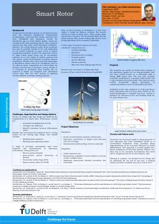
EC 130 B4 Initial Pilot Ground School Chapter 6 Tail Rotor Drive System and Tail Rotor
Chapter 6 - Tail Rotor Drive System and Tail Rotor Tail Rotor Drive System …..…………………………….…………...….… 6.3 Tail Rotor Drive Shaft Assembly ..……………………………………….. 6.4 Tail Rotor Drive System Technical Characteristics ..……......………. 6.6 Rear Tail Rotor Drive Shaft ……………………….………………………. 6.7 Tail Rotor Gear Box ...……………………………………………………… 6.9 Tail Rotor Gear Box Chip Detection …………………………………….. 6.12 Tail Rotor Gear Box Chip Caution Light ……………………………….. 6.14 Tail Rotor - Fenestron …………………………………………………….. 6.15 Tail Rotor Blade Attachment Components ……...…………………….. 6.17 Tail Rotor Control Failure ...………………………...……… 6.22, 6.23 & 6.25 Review Questions ………………………………………………………….. 6.26 6.2
Tail Rotor Drive System TAIL ROTOR DRIVE GENERAL 6.3
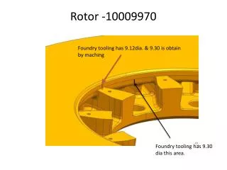
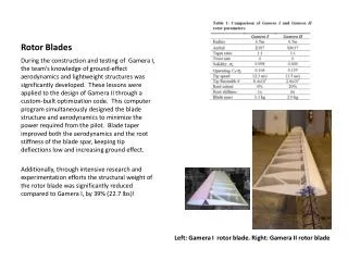
Tail Rotor Drive Shaft Assembly Rear Light Aluminum Alloy Drive Shaft Middle Light Aluminum Alloy Drive Shaft Forward Stainless Steel Drive Shaft NO. 1 BEARING is at the rear of the assembly. The tail rotor drive shaft is similar to that found on the AS350. The middle long shaft is shorter, and it couples via an adapter to an aluminum alloy shaft which connects to the tail rotor gear box. 6.4
Tail Rotor Drive Shaft Assembly Short Forward Shaft - Stainless Steel Long Shaft - Aluminum Alloy Coupling Flange Short Rear Shaft - Aluminum Alloy 6.5
Tail Rotor Drive System Technical Characteristics 6.6
Forward Rear Tail Rotor Drive Shaft 6.7
Forward T/R Rear Shaft input into T/R Gear Box Input speed is approximately 6000 rpm 6.8
Tail Rotor Gear Box 3584 RPM 6000 RPM Splash lubricated with MIL-L-6086C The “Shell” Trademark is Prohibited. [ This is due to foaming caused by an additive in Shell mineral oil which actually decreases the lubricating properties of the oil. ] 6.9
Tail Rotor Gear Box 6.10
Forward Top View of Tail Rotor Gear Box Single Stage Angle Reduction 6.11
MGB CHIP Tail Rotor Gear Box Chip Detection Oil Filler Cap Oil Level Sight Glass Electrical Magnetic Chip Plug 6.12
TGBCHIP WARNING PANEL CORRECTIVE ACTIONS Metal particles in TGB oil circuit 6.13 Flight Manual - Emergency Procedures - Page 3-14
TGBCHIP WARNING PANEL CORRECTIVE ACTIONS Avoid prolonged hovering CONTINUE FLIGHT Metal particles in TGB oil circuit 6.14 Flight Manual - Emergency Procedures - Page 3-14
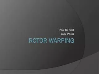
Tail Rotor - Fenestron The 10 aluminum alloy blades are asymmetrically spaced for noise reduction purposes and turn at approximately 3584 rpm. They have a clockwise rotation as viewed from the left. 6.15
Tail Rotor Pedal input to the tail rotor is via a flexible ball cable which then connects to a rigid control rod. There is no hydraulic boost to the tail rotor. 6.16
T/R Blade Attachment Components Pitch change spider Chinese weights Pitch change ball joint Tension - torsion straps made of stainless steel 6.17
TAIL ROTOR CONTROL FAILURE Symptom: the helicopter will yaw to the left with a rotational speed depending on the amount of power and the forward speed set at the time of the failure. • Hover - IGE (or OGE in HV diagram) 6.19 Flight Manual - Emergency Procedures - Page 3 - 5
TAIL ROTOR CONTROL FAILURE Symptom: the helicopter will yaw to the left with a rotational speed depending on the amount of power and the forward speed set at the time of the failure. • Hover - IGE (or OGE in HV diagram) LAND IMMEDIATELY 1. Twist Grip ….IDLE STOP POSITION 2. Collective ….INCREASE to cushion touch-down Flight Manual - Emergency Procedures - Page 3 - 5 6.20
TAIL ROTOR CONTROL FAILURE Symptom: the helicopter will yaw to the left with a rotational speed depending on the amount of power and the forward speed set at the time of the failure. • Hover - IGE (or OGE in HV diagram) LAND IMMEDIATELY 1. Twist Grip ….IDLE STOP POSITION 2. Collective ….INCREASE to cushion touch-down • Hover - OGE (Clear area, out of HV diagram) Flight Manual - Emergency Procedures - Page 3 - 5 6.21
(Continued TAIL ROTOR CONTROL FAILURE Symptom: the helicopter will yaw to the left with a rotational speed depending on the amount of power and the forward speed set at the time of the failure. • Hover - IGE (or OGE in HV diagram) LAND IMMEDIATELY 1. Twist Grip ….IDLE STOP POSITION 2. Collective ….INCREASE to cushion touch-down • Hover - OGE (Clear area, out of HV diagram) Simultaneously, 1. Collective ….REDUCE depending upon available height 2. Cyclic ….FORWARD to gain speed 3. Cyclic ….ADJUST to set IAS to Vy and control yaw LAND AS SOON AS POSSIBLE If a go-around has been performed, carry out an autorotative landing on a suitable area as landing procedure. Flight Manual - Emergency Procedures - Page 3 - 5 6.22
TAIL ROTOR CONTROL FAILURE WARNING SAFE AUTOROTATIVE LANDING CAN NOT BE WARRANTED IN CASE OF A FAILURE IN HOGE BELOW THE TOP POINT OF THE HV DIAGRAM (REFER TO SECTION 5) OR IN CONFINED AREA. Flight Manual - Emergency Procedures - Page 3 - 5 6.23
TAIL ROTOR CONTROL FAILURE • In Cruise Flight Flight Manual - Emergency Procedures - Page 3 - 5 6.24
TAIL ROTOR CONTROL FAILURE • In Cruise Flight 1. Cyclic ….ADJUST to set IAS to Vy and control yaw 2. Collective ….REDUCE to avoid sideslip LAND AS SOON AS POSSIBLE APPROACH AND LANDING Carry out an autorotative landing on a suitable area as landing procedure. Flight Manual - Emergency Procedures - Page 3 - 5 6.25
Review Questions 6.26
45. What is the tail rotor drive shaft connected to on the forward end? • Engine reduction gearbox via a stainless • steel shaft and flex-couplings.
46. What is the aft tail rotor drive shaft connected to on the aft end? D. The Tail Gearbox via flex-couplings.
47. What is the forward drive shaft constructed of? C. Stainless steel
48. What is the middle shaft constructed of? B. Aluminum alloy
49. What type of reduction is used in the tail rotor gear box? D. Single stage angle reduction.
50. What oil monitoring devices are used in the tail rotor gearbox? B. CHIP TGB light and oil level sight glass.
51. The tail rotor pitch change bellcrank moves a certain component on the tail rotor output shaft to cause pitch changes in the tail rotor. What component does this? A. Pitch change spider.
52. What are the tail rotor blades made of? D. Aluminum alloy.
53. Why are the ten asymmetrical fenestron blades staggered? D. To reduce the noise level.
EC 130 B4 Initial Pilot Ground School End of Chapter 6 Tail Rotor Drive System and Tail Rotor