Download
1 / 46
480 likes | 1.09k Views
Stator AND ROTOR Winding Ground Protection Failures. CLYDE MAUGHAN, PRESIDENT MAUGHAN GENERATOR CONSULTANTS SCHENECTADY, NEW YORK Phone: 518 377 5351 Email: clyde@maughan.com Web: clyde.maughan.com. A PERSONAL NOTE. DURING A 63-year career in generators . . .

E N D
Stator AND ROTOR Winding Ground Protection Failures CLYDE MAUGHAN, PRESIDENT MAUGHAN GENERATOR CONSULTANTS SCHENECTADY, NEW YORK Phone: 518 377 5351 Email: clyde@maughan.com Web: clyde.maughan.com
A PERSONAL NOTE • DURING A 63-year career in generators . . . • “I had GROWN OLD AND HADN’T NOTICED” • but noticed January 5 of this year • “Minor stroke” (IF THERE IS SUCH A THING) • LEFT SIDE OF BODY INITIALLY PRETTY MUCH PARALYZED • Recovered well, but everything is MUCH harder to do
Topic of this presentation DEFICIENT STATOR & ROTOR WINDING GROUND PROTECTION
RESULT OF THIS RELAY DEFICIENCY ON STATORS • MYSELF • I HAVE SUFFERED THROUGH 4 STATOR WINDING FAILURES DURING A RECENT TWO-YEAR PERIOD • EACH WAS ON THE NEUTRAL END OF THE WINDING • IN EACH CASE, THE GROUND RELAY DID NOT TRIP UNIT • EACH FAILURE WAS MASSIVE AND COSTLY AND LONG • OTHERS (from IGTC) • TWO ADDITIONAL SIMILAR FAILURES • 1400 MW NUCLEAR UNIT • 200 MW FOSSIL
ROOT CAUSE OF THE WORST 5 OF THESE 6 FAILURES • TWO ARE KNOWN WITH HIGH CERTAINTY • FAILED JOINT WITHIN CONNECTION RING COPPER • FAILED BOLTED CONNECTION • THREE HAVE SUSPECTED CAUSES • WATER-COOLED STATOR BAR STRAND LEAK • STATOR WINDING FAILURE • CORE LAMINATION INSULATION FAILURE
STATOR WINDING GROUND RELAY PROTECTION • ELECTRO-MECHANICAL (ON ALL 6 GENERATORS) • BEEN IN USE FROM THE BEGINNING OF POWER GENERATION • ENERGIZED BY WINDING VOLTAGE, AND AS A RESULT . . . • MONITORS ONLY THE TOP ~95% OF WINDING • LEAVES COMPLETELY UNMONITORED AND UNPROTECTED EVEN TO SOLID GROUND • 50% OF THE CONNECTIONS • ALL THE STATOR BARS CONNECTED TO NEUTRAL • DIGITAL • EXTERNALLY POWERED BY TWO DIFFERENT METHODS • 3RD HARMONIC (MONITORS ALMOST ALL OF WINDING) • SIGNAL INJECTION (MONITORS 100% OF WINDING) • WILL RETURN TO THIS TOPIC
FIVE FAILURES DETAILS OF ACTUAL FAILURES AND ROOT CAUSES NOT DISCUSSED (NOT GERMAIN TO THE TOPIC AND MY OPINIONS COULD GET ME IN TROUBLE)
COST IMPACT OF FAILURE OF GROUND RELAY TO INTERRUPT • NO KNOWN TESTS PERFORMED TO TRY TO QUANTIFY IMPACT OF INOPERATIVE RELAY • NO OBVIOUS AND PRACTICAL WAY TO TEST AND QUANTIFY • CAN ONLY ESTIMATE, BUT ALL VALUES WILL BE HUGE • SO, TRYING TO QUANTIFY WITH (MY 63 YEARS OF) ENGINEERING JUDGMENT (OPINION?) . . .
COSTS OF THE 4 LARGE FAILURES (A ROUGH GUESS) • ACTUAL • REPAIRS • ($ MILLION): 18, 40, 25, 21 = $104,000,000 • LOSS OF GENERATION • ($ MILLION): 120, 150, 8, 100 = $378,000,000 • TOTAL = $482,000,000 • ESTIMATE WITH FUNCTIONING GROUND RELAY • REPAIRS • APPROXIMATE ($ MILLION): 5, 12, 3, 10 = $30,000,000 • LOSS OF GENERATION • APPROXIMATE ($ MILLION): 30, 40, 8, 50 = $128,000,000 • DELTA (SAVINGS WITH A FUNCTIONING GROUND RELAY) • REPAIRS: 13, 28, 22,11 = $74,000,000 • LOSS OF GENERATION: 90, 110, 0, 50 = $250,000,000 • TOTAL SAVING: $324,000,000 • IF I AM OFF BY AN ORDER OF MAGNITUDE: $32,400,000
2 WINDING FAILURES WHERE THE GROUND RELAY FUNCTIONED IN EACH CASE, REPAIRS WERE RELATIVELY VERY SMALL
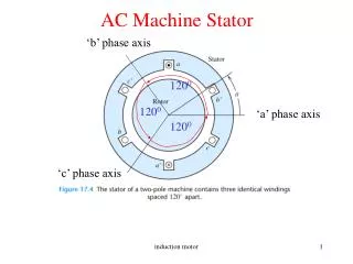
TYPICAL STATOR WINDING GROUNDING SYSTEM • typically Y-connected • high-impedance groundINGthrough a distribution transformer • impedance is controlled by the magnitude of the resistor connected across the transformer • impedance is selected to allow a NON-DESTRUCTIVE maximum of 3-10 amperes in the event of a ground at the high voltage end of the stator winding
HISTORIC RELAY PROTECTION • across the resistor is placed an electromechanical relay, 59GN • This relay is powered by the voltage of the stator winding • The characteristics of this electrical circuit and relay are such that the relay does not respond to the voltage of the bottom ~5% of the stator winding
59GN SYSTEM DEFICIENCY • SEVERE weakness THAT has been recognized for many years • By the early 1970s, in Europe most generators larger than 100 MW were protected by a 59gn relay and a 3rdharmonic relay, 59THD • This combined relay system protects 100% of the stator winding • This deficiency was SLOW TO BE RECOGNIZED IN USA • in 1980, 3rd harmonic relay protection was applied in the USA • BUT MOST OF USA GENERATORS APPARENTLY STILL USE only THE 59GN PROTECTION SYSTEM
WEAKNESS OF THE COMBINED 59GN/59THD RELAY SYSTEM • requires initial calibration with the generator operating off-line and on-line in order to properly set the relay responses • this calibration work can involve significant cost and inconvenience to the planT • In addition, some generating units may not produce sufficient third-harmonic voltages to allow reliable ground fault protection schemes based on 3rd harmonic signals • Finally, the 3rd harmonic relay system has been found to occasionally perform unreliably due to subtle changes in the power system 3rd harmonic voltages over timE
SOLUTION: INJECTION RELAY – 64S • RECENT trend toward developing and installing voltage injection relay • RELAY 64S • A sub-harmonic sinusoidal voltage is injected continuously • typically at 15 or 20 Hz (on 60 Hz systems) • The resultant sub-harmonic current is measured via the 64S relay • if a ground fault occurs anywhere in the 3 phases of the stator winding, the relay operates
64S RELAY CHARACTERISTICS • functional UNDER ALL CONDITIONS • shut down at standstill or turning gear, during startup, and at-speed off-line or on-line • PERFORMANCE IS independent of power system voltage, load current or frequency • 64S relay system integrates over a half cycle of the sub-harmonic frequency • there is no contribution from the signals of system base frequency and harmonics, e.g., 60 Hz, 120 Hz, 180 Hz • Thus these frequencies do not influence the 64S relay performance
COSTS • The cost associated with providing and maintaining a reliable injection source is An obvious disadvantage • BASE COST PERHAPS IN THE ORDER OF $8000 • NEW SYSTEM DESIGN, MATERIAL AND INSTALLATION COSTS MAYBE AN ORDER OF MAGNITUDE MORE • But this disadvantage may be small compared to the costs associated with calibration efforts required on the 3rd harmonic relay system • AND COMPARED TO THE POTENTIAL COSTS ASSOCIATED WITH AN UNPROTECTED FAILURE, INFINITESIMAL
SOURCES FOR RELAY SYSTEMS • Schweitzer Engineering Laboratories • RogeRioScharlach • WHO PROVIDED THE RELAY SYSTEM DRAWINGS • AND PROVIDED ME AN EDUCATION ON PROTECTIVE RELAYS • BECKWITH ELECTRIC • WHO HAVE VERIFIED WHAT I AM SAYING ON RELAYING IS (SADLY) CORRECT • SIEMENS • OTHERS
RELAY PROTECTION SUMMARY • 59GN relay – HISTORIC • gives reliable protection, but only on the top ~95% of the winding. • 59THD relay – THIRD HARMONIC • does not protect the mid-portion of the winding • HAS INHERENT RELIABILITY PROBLEMS • 64s relay – INJECTION • REQUIRES the signal generator • can alone reliably protect the entire winding • detectSopen circuits in the grounding transformer primary or secondary • is self-protecting for a grounding relay system problem or loss of injection voltage source
RECOMMENDATION !!! • OPERATORS OF GENERATORS • review your stator winding ground protection relay systems • ON any generator protected only by the 59GN relay . . . • upgradE to incorporate 100% stator winding ground protection • PROBABLY THE INJECTION RELAY 64S
INPUT FROM NATIONAL ELECTRICAL COIL WEB SITE (IGTC) www.generatortechnicalforum.org
WEB SITE FEEDBACK • SEVERAL RESPONSES • THREE ADDITIONAL BOTTOM 5% FAILURES • SEVERAL PROBLEMS AND CONCERNS WITH 3RD HARMONIC RELAY SYSTEM THAT DETECT GROUNDS IN BOTTOM 5% • AND A CONCERN RAISED WITH RESPECT TO IEEE STANDARDS
A BASIC CONCERN RELATIVE TO IEEE GUIDES • IEEE C37.101-2006 Guide for Generator Ground Protection • STATORS • IEEE C37.102-2012, Guide for AC Generator Protection • STATORS AND ROTORS
IEEE GUIDE C37.101-2006 Generator Ground Protection, page 29 – STATORS "The importance of detecting ground faults close to the neutral point of the generator is not dependent on the need to trip because of fault current magnitude, since it may be negligible and will not, in general, cause immediate damage. If a second ground fault occurs, severe damage may be sustained by the machine because this may result in a short-circuit current not limited by the grounding impedance.”
IEEE C37.102-2012, Guide for AC Generator Protection, page 46 – ROTORS “The field circuit of a generator is an ungrounded system. As such, a single ground fault will not generally affect the operation of a generator. However, if a second ground fault occurs, a portion of the field winding will be short-circuited, thereby producing unbalanced air gap fluxes in the machine. These unbalanced fluxes may cause rotor vibration that may quickly damage the machine; also, unbalanced rotor winding and rotor body temperatures caused by uneven rotor winding currents may cause similar damaging vibrations.”
BOTH IEEE GUIDES • OVERLOOK AN UNFORTUNATELY COMMON MODE OF FAILURE OF EACH, i.e., THE BROKEN CONDUCTOR (AND COIL SHORTS ON ROTORS) • ALWAYS A PROBLEM AND OFTEN A MASSIVE PROBLEM STATORS (DISCUSSED ABOVE) • BUT ALSO ON ROTORS . . .
THESE IEEE GUIDE ASSUMPTION ERRORS . . . • RESULT FROM • INSUFFICIENT COMMUNICATION BETWEEN RELAY AND GENERATOR PERSONNEL • INSUFFICIENT INVOLVEMENT OF OEM GENERATOR ENGINEERS IN WRITING THE GUIDES • DESPERATELY NEED TO BE FIXED • BUT NOTICE C37.102-2012 WAS JUST REISSUED • NEITHER IS SCHEDULED TO BE UPDATED UNTIL 2018 (OR LATER) • WILL BE AN ONGOING CONCERN
AN OBSERVATION . . . • COMMUNICATIONS ISSUE • RELAY PEOPLE DO NOT UNDERSTAND GENERATORS, AND • GENERATOR PEOPLE DO NOT UNDERSTAND RELAYS • SO GENERATORS OPERATE WITH AN IDENTIFIED (AND CORRECTABLE) DEFICIENT RELAY SYSTEM
AN ASSIGNMENT . . . • TALK TO YOUR RELAY PEOPLE • (AND MAYBE GIVE THEM A COPY OF THIS PAPER) • GET YOUR GENERATORS EQUIPPED WITH PROPER STATOR AND ROTOR RELAY GROUND PROTECTION • (AND MAYBE FIX THE IEEE GUIDES)
TO CONCLUDE . . . • MY END-OF-CAREER GOALS • GET EVERY UTILITY TO INSTALL 100% STATOR WINDING GROUND PROTECTION ON EVERY GENERATOR • GET THE IEEE STANDARDS COMMITTEES TO CORRECT THE STATOR AND ROTOR GROUND RELAY PROTECTION DEFICIENCIES • THAT IS NOT ASKING TOO MUCH, IS IT? (WELL, MAYBE, JUST A LITTLE.)
Stator AND ROTOR Winding Ground Protection Failures CLYDE MAUGHAN, PRESIDENT MAUGHAN GENERATOR CONSULTANTS SCHENECTADY, NEW YORK Phone: 518 377 5351 Email: clyde@maughan.com Web: clyde.maughan.com