Download
1 / 27
290 likes | 523 Views
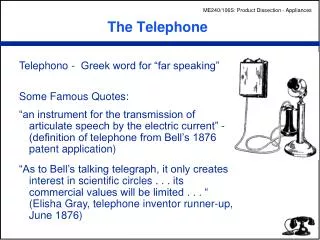
THE TELEPHONE NETWORK. The modern telephone network was developed to provide basic telephone service, which involves the two-way, real-time transmission of voice signals. In its most basic form, this service involves the transfer of an analog signal of a

E N D
THE TELEPHONE NETWORK • The modern telephone network was developed to provide basic telephone service, which involves the two-way, real-time transmission of voice signals. In its most basic form, this service involves the transfer of an analog signal of a nominal bandwidth of 4 kHz across a sequence of transmission and switching facilities. Telephone networks operate on the basis of circuit switching. Initially, circuit switching involved the setting up of a physical path from one telephone all the way across the network to the other telephone, as shown in Fig 4.30. At the telephone offices operators would make physical connections that would allow electric current to flow from one telephone to the other. • The physical resources, such as wires and switch connections, were dedicated to the call for its entire duration. Modern digital telephone networks combine this circuit-switching.
Fig 4.31 shows the three phases of connection-oriented communications. When a user picks up the phone, a current flow is initiated that alerts equipment in a switch at the local telephone office of a call request. • The switch prepares to accept the dialed digits and then provides the user with a dial tone. The user then enters the telephone number either by turning a dial that generates a sequence of pulses or by pushing a series of buttons that generates a sequence of tones. • switch equipment converts these pulses or tones into a telephone number. • In North America each telephone is given a 10-digit number according to the North American numbering plan.
The first three digits are the area code, the next three digits are the central office code, and the last four digits are the station number. The first six digits of the telephone number uniquely identify the central office of the destination telephone. • To set up a call, the source switch uses the • telephone signaling network to find a route and allocate resources across the network to the destination office. • This step is indicated by the propagation of signaling messages in Fig 4.31. The destination office next alerts the destination user of an incoming call by ringing the phone. This ring is sent back to the source telephone, and conversation can begin when the destination phone is picked up.
The call is now in the message transfer phase. The call is terminated and the resources released when the users hang up their telephones. • The call setup procedure involves finding a path from the source to the destination. Fig 4.32a shows a typical arrangement in a metropolitan area. • Central offices are connected by high-speed digital transmission lines that correspond to a group of trunks. If the two telephones are connected to the same central office, that is, the two phones are attached to switch A, then they are connected directly by the local switch. If the two telephones are connected to different central offices (that is, A and B), then a route needs to be selected.
In the United States the telephone network is divided into local access and transport areas (LATAs) that are served by the local exchange carriers (LECs). • The LECs consist of regional bell operating companies (RBOCs) such as BellSouth, Southwestern Bell, and Bell Atlantic, and independent carriers such as GTE. • Communication between LATAs is provided by separate independent interexchange carriers (IXCs), that is, long-distance service providers such as AT&T and MCI. Figure 4.32b shows how long distance calls are routed from a switch in the LATA to a facility that connects the call to the network of one of a number of interexchange carriers. The call is then routed through the network of the interexchange carrier to the destination LATA and then to the destination telephone
Now let us consider the end-to-end path that is set up between the source and the destination telephones. In the majority of cases, the telephones are connected to their local telephone office with a twisted pair of copper wires. • The voice signal flows in analog form from the telephone to the telephone office. The voice signal is converted into digital form using PCM at the line card interface where the • copper wires connect to the local telephone switch. The digitized voice signal flows from that point onward as a sequence of PCM samples over a path that has been set up across the network. • This path consists of reserved time slots in transmission links that use TDM. The transmission links connect digital switches in which TSI arrangements have been made during call set up. Finally, at the destination switch the received PCM signal is converted back to analog form and transmitted to the destination telephone over the pair of copper wires. • The pair of copper wires that connect the user telephones to their local offices is called the ``last mile,'' which constitutes the remaining obstacle to providing end-to-end digital connectivity
Transmission Facilities • The user's telephone is connected to its local telephone office by twisted-pair copper wires that are called the local loop. The wire pairs are stranded into groups, and the groups are combined in cables that can hold up to 2700 pairs. • Wire pairs connect to the telephone office at the distribution frame as shown in Fig 4.33. From the local office the feeder cables extend in a star topology to the various geographic serving areas. • Each feeder cable connects to a serving area interface. Distribution cables in turn extend in a star topology from the serving area interface to the pedestals that connect to the user's telephone. • In the local loop a single pair of wires carries the information in both directions, from the user to the local switch and from the local switch to the user. Inside the network a separate pair of wires is used for each direction of signal flow.
As shown in Figure 4.34, at the interface to the switch a device called a hybrid transformer converts the signals from the incoming wire pair to the four-wire connection that is used inside the network. • These hybrid transformers tend to reflect some of the arriving signal resulting in echoes that under certain conditions can be disturbing to speakers and that can impair digital transmission. • For these reasons, echo-cancellation devices have been developed that estimate the echo delay and use a properly delayed and scaled version of the transmitted signal to cancel the arriving echoes.
The twisted-wire pairs that connect the user to the local switch can be used to carry high-speed digital signals using ADSL and other digital transmission technologies. • In many instances the feeder cable that connects the serving area interface to the local switch is being replaced with an optical fiber that carries TDM traffic. • In this case the service area interface carries out the conversion to and from PCM. As optical fiber extends closer to the user premises, the distance that needs to be covered by the twisted-wire pairs is reduced. • In the future this deployment of optical fiber is likely to be one of the approaches that will be used to provide much higher bit rates to the user premises.
In addition to handling the analog telephone traffic from its serving areas, a local telephone switching office must handle a multiplicity of other types of transmission lines. These include digital lines of various speeds from customers premises, private lines, foreign exchange lines, lines from cellar telephone networks, and high-speed digital transmission line to the backbone of the network. • A digital cross-connect system is used to organize the various types of lines that arrive and depart from a telephone office. A digital cross-connect (DCC) system is simply a digital TD switch that is used to manage the longer-term flows in a N/W. • Unlike the TD switches that deal with individual telephone calls, DCC systems are not controlled by the signaling process associated with call setup. Instead they are controlled by the network operator to meet network configuration requirements.
Fig 4.35 shows how a DCC system can be used to interconnect various types of traffic flows in a telephone central office. The local analog telephone • signals on the left side are digitized and then input into the DCC system. The other traffic on the left side are local digital traffic and digital trunks connected to other offices. • Some of these inputs are permanently connected as ``tie lines‘’ that interconnect customer sites; some of the other inputs may originate in other central offices and be permanently connected to foreign exchange lines that access an international gateway. Voice traffic that needs to be switched is routed. • From the input lines to a digital switch that is attached to the DCC system. The DCC system provides a flexible means for managing these connections on a semi permanent basis.
The transmission facilities between switches in the telephone network are becoming dominated by SONET-based optical transmission equipment using point-to-point and ring topologies as discussed earlier. • DCC systems can be combined with SONET transmission systems to configure the topology ``seen'' by the telephone switches during call setup. • As an example, in Fig4.36 we show a SONET network that has a ``stringy'' physical topology. The SONET tributaries can be configured using add-drop multiplexers and a DCC • system so tributaries interconnect the switches to produce the topology. • In particular note that the maximum number of hops between any pair of switches is two hops instead of the four hops in the physical topology. • One benefit of decreasing the number of hops between switches is to simplify the routing procedure that is implemented by the switches.
DCC and SONET equipment can also be combined to provide network recovery from faults. • For example, standby tributaries may be set up to protect against failures. Should a fault occur, the standby tributaries are activated to restore the original logical topology seen by the switches. This approach reduces the actions that the network switches must take in response to the failure.
End-to-End Digital Services • Since the inception of telephony, the telephone user has been connected to the telephone office by a pair of copper wires in the local loop. This last mile of the network has remained analog even as the backbone of the network was converted to all-digital transmission & switching. • In the mid-1970s it became apparent that the demand for data services would necessitate making the telephone network entirely digital as well as capable of providing access to a wide range of services including voice and data. In the early 1980s the CCITT developed the Integrated Services Digital Network (ISDN) set of standards for providing end-to-end digital connectivity
The ISDN standards define two interfaces between the user and the network as shown in Fig4.37. The purpose of the interfaces is to provide access to various services that are possibly supported by different networks. The basic rate interface (BRI) provides the user with two 64 kbps bearer (B) channels and one 16 kbps data (D) channel. The primary rate interface (PRI) provides users with 23B + 1 D channels in North America and Japan and 30B + 1 D channels in Europe. • The primary rate formats were clearly chosen to fit the T-1 and CEPT-1 frame formats in the digital multiplexing hierarchy.
Each B channel is bidirectional and provides a 64 kbps end-to-end digital connection that can carry PCM voice or data. The primary function of the D channel is to carry signaling information for the B channels at the interface between the user and the network. • The D channel can also be used to access a packet network. The D channel is 64kbps in the primary rate interface. Additional H channels have been defined by combining B channels to provide rates of 384 kbps (H0), 1.536 Mbps (H11), and 1.920 Mbps (H12).
The basic rate interface was intended as a replacement for the basic telephone service. In North America the associated transmission format over twisted-wire pairs was selected to operate at 160 kbps and use the band that is occupied by traditional analog voice. The two B channels could provide two digital voice connections, and the D channel would provide signaling and access to a packet network. • In practice, the 2B channels in the basic rate interface found use in digital videoconferencing applications and in providing access to Internet service providers at speeds higher than those available over conventional modems. • The primary rate interface was intended for providing access from user premises equipment such as private branch exchanges (PBXs) and multiplexers to the network.
ISDN was very slow in being adopted primarily because few services could use it. The growth of the Internet as a result of the World Wide Web has stimulated the deployment of ISDN as an alternative to telephone modems. • However, alternative ADSL transmission techniques for providing much higher speeds over the local loop are currently being introduced to meet the demand for high-speed Internet access. • These techniques coexist with the regular analog telephone signal and do not interact with the telephone network.
As the ISDN standard was being completed, the interest in high-definition television and high-speed data interconnection prompted new work on a broadband ISDN (BISDN) standard. The very high bit rate required by these applications necessitated access speeds much higher than those provided by ISDN. • The BISDN effort resulted in much more than an interface standard. An entirely new network architecture based on the connection-oriented transfer and switching of small fixed-length packets, known as asynchronous transfer mode (ATM), emerged as a target network for supporting a very wide range of services.