9-1 TELEPHONE NETWORK
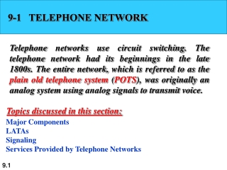
9-1 TELEPHONE NETWORK. Telephone networks use circuit switching. The telephone network had its beginnings in the late 1800s. The entire network, which is referred to as the plain old telephone system ( POTS ), was originally an analog system using analog signals to transmit voice.

9-1 TELEPHONE NETWORK
E N D
Presentation Transcript
9-1 TELEPHONE NETWORK Telephone networks use circuit switching. The telephone network had its beginnings in the late 1800s. The entire network, which is referred to as the plain old telephone system (POTS), was originally an analog system using analog signals to transmit voice. Topics discussed in this section: Major Components LATAsSignaling Services Provided by Telephone Networks
Local Loops, Trunks • One component of the telephone network is the local loop, a twisted-pair cable that connects the subscriber telephone to the nearest end office or local central office. • The local loop, when used for voice, has a bandwidth of 4000 Hz (4 kHz). • The first three digits of a local telephone number define the office, and the next four digits define the local loop number. • Trunks • Trunks are transmission media that handle the communication between offices. • A trunk normally handles hundreds or thousands of connections through multiplexing. • Transmission is usually through optical fibers or satellite links. • loops or trunks and allows a connection between different subscribers.
Switching Offices • To avoid having a permanent physical link between any two subscribers, • the telephone company has switches located in a switching office. A switch connects several local
LATAs • Local access transport areas • the United States was divided into more than 200 local-access transport areas (LATAs). • A LATA can be a small or large metropolitan area. • A small state may have one single LATA; a large state may have several LATAs. • A LATA boundary may overlap the boundary of a state
Note Intra-LATA services are provided by local exchange carriers. Since 1996, there are two types of LECs: incumbent local exchange carriers and competitive local exchange carriers.
Intra LATA Communication • Communication inside a LATA is handled by end switches and tandem switches. • A call that can be completed by using only end offices is considered toll-free. • A call that has to go through a tandem office (intra-LATA toll office) is charged.
Inter-LATA Services • The services between LATAs are handled by interexchange carriers (IXCs). • These carriers, sometimes called long-distance companies, provide communication services between two customers in different LATAs. • these services can be provided by any carrier, including those involved in intra-LATA services. Carriers providing inter-LATA services include AT&T, MCI, WorldCom, Sprint, and Verizon. • A telephone call going through an IXC is normally digitized, with the carriers using several types of networks to provide service.
Points of Presence (POP) • intra-LATA services can be provided by several LECs (one ILEC and possibly more than one CLEC). • We also said that inter-LATA services can be provided by several IXCs. • These carrier connect with each other via a switching office called a point of presence (POP). • Each IXC that wants to provide interLATAservices in a LATA must have a POP in that LATA. • The LECs that provide services inside the LATA must provide connections so that every subscriber can have access to all POPs. Figure 9.3 illustrates the concept.
Note The tasks of data transfer and signaling are separated in modern telephone networks: data transfer is done by one network, signaling by another.
Signaling Network • The user telephone or computer is connected to the signal points (SPs). • The link between the telephone set and SP is common for the two networks. • The signaling network uses nodes called signal transport ports (STPs) that receive and forward signaling messages. • The signaling network also includes a service control point (SCP) that controls the whole operation of the network.
Signaling System Seven (SS7) • The protocol that is used in the signaling network is called Signaling System Seven (SS7). • It is very similar to the five-layer Internet model (TCP/IP Model) but the layers have different names, as shown in Figure 9.5.
Layers in SS7 • Physical Layer: MTP Level 1 The physical layer in SS7 called message transport part (MTP) level I uses several physical layer specifications such as T-l (1.544 Mbps) and DCa (64 kbps). • Data Link Layer: MTP Level 2 The MTP level 2 layer provides typical data link layer services such as packetizing, using source and destination address in the packet header, and CRC for error checking. • Network Layer: MTP Level 3 The MTP level 3 layer provides end-to-end connectivity by using the datagram approach to switching. Routers and switches route the signal packets from the source to the destination.
Layers in SS7 • Transport Layer: SCCP The signaling connection control point (SCCP) is used for special services such as SaO-call processing. • Upper Layers: TUP, TCAP, and ISUP There are three protocols at the upper layers. • Telephone user port (TUP) is responsible for setting up voice calls
9-2 DIAL-UP MODEMS Traditional telephone lines can carry frequencies between 300 and 3300 Hz, giving them a bandwidth of 3000 Hz. All this range is used for transmitting voice, where a great deal of interference and distortion can be accepted without loss of intelligibility. Topics discussed in this section: Modem Standards
Note Modem stands for modulator/demodulator.
V.32 Modem • The V.32 modem uses a combined modulation and encoding technique called trelliscoded modulation. • Trellis is essentially QAM plus a redundant bit. • The data stream is divided into 4-bit sections. Instead of a quadbit (4-bit pattern), however, a pentabit (5-bit pattern) is transmitted. • The value of the extra bit is calculated from the values of the data bits. • The extra bit is used for error detection. • The Y.32 calls for 32-QAM with a baud rate of 2400. Data rate is 9600 bps.
V.32bis Modem • The V.32bis modem was the first of the ITU-T standards to support 14,400-bps transmission. • The Y.32bis uses 128-QAM transmission (7 bits/baud with I bit for error control) at a rate of 2400 baud (2400 x 6 = 14,400 bps). • Modem can adjust its speed upward or • downward depending on the quality of the line or signal.
9-3 DIGITAL SUBSCRIBER LINE After traditional modems reached their peak data rate, telephone companies developed another technology, DSL, to provide higher-speed access to the Internet. Digital subscriber line (DSL) technology is one of the most promising for supporting high-speed digital communication over the existing local loops. Topics discussed in this section: ADSL ADSL Lite HDSL SDSLVDSL
Note ADSL is an asymmetric communication technology designed for residential users; it is not suitable for businesses.
ADSL • The first technology in the set is asymmetric DSL (ADSL). • ADSL, like a 56K modem, provides higher speed (bit rate) in the downstream direction (from the Internet to the resident) than in the upstream direction (from the resident to the Internet). • That is the reason it is called asymmetric. Unlike the asymmetry in 56K modems, the designers of ADSL specifically divided the available bandwidth of the local loop unevenly for the residential customer. • The service is not suitable for business customers who need a large bandwidth in both directions.
Note The existing local loops can handle bandwidths up to 1.1 MHz.
Note ADSL is an adaptive technology. The system uses a data rate based on the condition of the local loop line.
Discrete Multitone Technique • The modulation technique that has become standard for ADSL is called the discrete multitonetechnique (DMT) which combines QAM and FDM. • There is no set way that the bandwidth of a system is divided. • Each system can decide on its bandwidth division. • Typically, an available bandwidth of 1.104 MHz is divided into 256 channels. • Each channel uses a bandwidth of 4.312 kHz, Figure 9.11 shows how the bandwidth can be divided into the following: • Voice. Channel 0 is reserved for voice communication. • Idle. Channels 1 to 5 are not used and provide a gap between voice and data communication.
Discrete Multitone Technique • Upstream data and control. • Channels 6 to 30 (25 channels) are used for upstream data transfer and control. • One channel is for control, and 24 channels are for data transfer. • However, the data rate is normally below 500 kbps because some of the carriers are deleted at frequencies where the noise level is large. • Downstream data and control. • Channels 31 to 255 (225 channels) are used for downstream data transfer and control. • One channel is for control, and 224 channels are for data. • If there are 224 channels, we can achieve up to 224 x 4000 x 15, or 13.4 Mbps. However, the data rate is normally below 8 Mbps because some of the carriers are deleted at frequencies where the noise level is large.
ADSL Lite • The installation of splitters at the border of the premises and the new wiring for the data line can be expensive and impractical enough to dissuade most subscribers. • A new version of ADSL technology called ADSL Lite (or Universal ADSL or splitterless ADSL) is available for these subscribers. • This technology allows an ASDL Lite modem to be plugged directly into a telephone jack and connected to the computer • The splitting is done at the telephone company.
HDSL • The high-bit-rate digital subscriber line (HDSL) was designed as an alternative to the T-lline (1.544 Mbps). • The T-1line uses alternate mark inversion (AMI) encoding, which is very susceptible to attenuation at high frequencies. • This limits the length of a T-l line to 3200 ft (1 km). • A repeater is necessary, which means • increased costs. • HDSL uses 2B1Q encoding which is less susceptible to attenuation. • A data rate of 1.544 Mbps (sometimes up to 2 Mbps) can be achieved without repeaters up to a distance of 12,000 ft.
SDSL (Symmetric DSL) • SDSL is a one twisted-pair version of HDSL. • It provides full-duplex symmetric communication supporting up to 768 kbps in each direction. • SDSL, which provides symmetric communication, can be considered an alternative to ADSL. • ADSL provides asymmetric communication, with a downstream bit rate that is much higher than the upstream bit rate. • Although this feature meets the needs of most residential subscribers, it is not suitable for businesses that send and receive data in large volumes in both directions.
VDSL • The very high-bit-rate digital subscriber line (VDSL), an alternative approach that is similar to ADSL, uses coaxial, fiber-optic, or twisted-pair cable for short distances. • The modulating technique is DMT. • It provides a range of bit rates (25 to 55 Mbps) for upstream communication at distances of 3000 to 10,000 ft. • The downstream rate is normally 3.2 Mbps.
9-4 CABLE TV NETWORKS The cable TV network started as a video service provider, but it has moved to the business of Internet access. In this section, we discuss cable TV networks per se; in Section 9.5 we discuss how this network can be used to provide high-speed access to the Internet. Topics discussed in this section: Traditional Cable Networks Hybrid Fiber-Coaxial (HFC) Network
Traditional Cable TV • Cable TV started to distribute broadcast video signals to locations with poor or no reception in the late 1940s. • It was called community antenna TV (CATV) because an antenna at the top of a tall hill or building received the signals from the TV stations and distributed them, via coaxial cables, to the community. • The cable TV office, called the head end, receives video signals from broadcasting stations and feeds the signals into coaxial cables. • There could be up to 35 amplifiers between the head end and the subscriber premises.
Note Communication in the traditional cable TV network is unidirectional.
Hybrid Fiber-Coaxial (HFC) Network • The second generation of cable networks is called a hybrid fiber-coaxial (HFC) network. • The network uses a combination of fiber-optic and coaxial cable. • The transmission medium from the cable TV office to a box, called the fiber node, is optical fiber; • From the fiber node through the neighborhood and into the house is still coaxial cable.
Note Communication in an HFC cable TV network can be bidirectional.