Download
1 / 48
520 likes | 744 Views
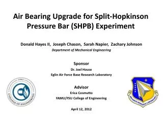
Air Bearing Upgrade for Split-Hopkinson Pressure Bar (SHPB) Experiment. Donald Hayes II, Joseph Chason, Sarah Napier, Zachary Johnson Department of Mechanical Engineering Sponsor Dr. Joel House Eglin Air Force Base Research Laboratory Advisor Erica Cosmutto

E N D
Air Bearing Upgrade for Split-Hopkinson Pressure Bar (SHPB) Experiment Donald Hayes II, Joseph Chason, Sarah Napier, Zachary Johnson Department of Mechanical Engineering Sponsor Dr. Joel House Eglin Air Force Base Research Laboratory Advisor Erica Cosmutto FAMU/FSU College of Engineering April 12, 2012
Overview • Introduction • Concept Generation & Selection • Final Concept • Components • Functional Diagram • Results & Discussion • Project Budget • Safety Concerns • Conclusion • Acknowledgements • Questions
Introduction: SHPB Basics Striker Mechanism Incident Bar / Strain Gauges / Bushings Material Sample Transmitter Bar / Strain Gauges / Bushings Momentum Trap Initial Strain Pulse Transmitted Pulse Reflected Pulse
Introduction: SHPB Basics Striker Mechanism Strain Gauges Material Sample Strain Gauges Momentum Trap Data Acquisition System Data
Introduction: Needs Assessment • Research air bearings for existing 5/8 inch diameter journal bearing system • Develop: • Bar alignment method • System upgrade from journal bearings to air bearings • Determine efficiency of air bearings over journal bearings
Introduction: Objectives • Analyze SHPB design based on use of air bearings • Analyze: • Hardware cost • Interface requirements • Installation procedures • Impact on bar geometry • Assess strain gauge technology • Develop procedure to align bars • Design a working prototype to show knowledge of system • Remain within $2500 budget
Generating Concepts: Methodology • Break system into base components • Treat components as individual systems • Generate multiple solutions per system • Determine most suitable components • Combine and implement into design
Generating Concepts: Components & Concerns • SHPB Components • Base Structure • Striker Mechanism • Incident & Transmission Bars • Strain Gauges • Air Bushings • Momentum Trap • Air Supply System • Concerns • Bar Alignment Method • Data Acquisition
Generating Concepts: Criteria • Portability • Scalability • Accuracy • Data Quality • Ease of Use • Cost • Weight • Size • Simplicity • Durability
Selecting Concepts Portability Data Quality Mass Simplicity Scalability Ease of use Cost Size Durability Accuracy Score
Components: Striker Mechanism McMaster Carr 336 ozf. Striker bar tube Striker bar Solenoid
Components: Air Bushings New Way Air Bearings 0.75” Inner Diameter 30 lb. Radial Load Bushing block housing Air line Air bushing
Components: Strain Gauges and Material Sample Strain gauges
Components: Strain Gauges and Material Sample Vishay Micromeasurements Gauge factor ≈ 2 Resistance = 120 Ω Located 6” from sample Strain gauges
Components: Strain Gauges and Material Sample Copper specimen ~ 0.3” diameter ~ 0.3” thick
Final Concept Length = 8 ft. Width = 7 in. Height = 3.5 in. Incident bar Copper specimen Striker bar mechanism Momentum trap Air bushing Strain gauges Transmitter bar
Functional Diagram 120 Volts AC Data Acquisition System Data Recording & Storage DC Power Supply Wheatstone Bridges Activation Switch Striker Mechanism Incident Bar / Strain Gauges / Bushings Material Sample Transmitter Bar / Strain Gauges / Bushings Momentum Trap Gas Supply Data Power Gas
Strain Pulse: Visualization Visualizing the Sample Copper Sample Steel Incident Bar Steel Transmitter Bar
Reduced Sample Area Increases Applied Stress Strain Pulse: Visualization Dsteel DCopper 0.75 in 0.31 in
Visualizing the Strain Pulse Surface: Von Mises Stress Yield Stress σy Copper ½ σy Steel
Analyzing Data • LabView hardware & software • 250 kHz Sampling rate • Measured Voltage Calculated Strain • Strain Waves Strain Energy • Geometric Definitions + Boundary Conditions • Material Description
Elastic Impulse Wave Area ∫dε*dt (s) Low sampling rate error
Discussion • Potential improvements in system • Use of stainless steel bars • Potential improvements in testing • Annealed copper specimen • Higher data rates • Used 250 kHz • Recommend 1 MHz • Implement friction imitation method to evaluate efficiencies between air bushings and journal bearings
Project Budget • Withinbudget • Total budget • $2,500 • Total expenditures • $2117 • Percentage under budget • 15%
Safety Concerns • Pinching/crushing fingers • Flying Fragments • Electrocution
Review • Analyzed: • SHPB design based on use of air bushings • Interface requirements • Installation procedures • Designed alignment tool • Impact on bar geometry
Review • Assessed strain gauge technology • Foil gauges sufficient • Semiconductor gauges if high accuracy required • Designed a working prototype that shows knowledge of system • Remained within $2500 budget • Total expenditures ≈ $2100
Conclusion • Accomplished major requirements! • Critical Factors • Segmented design • Ease of manufacture • Team cooperation • Excellent support
Acknowledgements We would like to thank the following people for their help and support which made this project a success… Dr. House – Eglin AFRL Dr. Shih – FAMU/FSU COE Dr. Kosaraju – FAMU/FSU COE, CAPS Dr. Dalban-Canassy – FAMU/FSU COE, ASC Dr. Hovsapian - CAPS Mr. Bob Walsh - NHMFL Mr. Dustin McRae – FAMU/FSU COE, NHMFL Dr. Solomon – FAMU/FSU COE Mr. Ryan Jantzen – FAMU/FSU COE, HPMI Mr. Bill Starch - ASC Dr. Hellstrom – FAMU/FSU COE, ASC THANK YOU!
Plastic Energy Derivation Stress σ = F/A Strain ε = (Li – Lo) / Lo Gauge Factor GF = [ (Ri - Ro) / Ro] / ε Data Strain ε (Ri) = [ (Ri - Ro) / Ro] / GF
Plastic Energy Derivation Strain in Specimen: dεavg/ dt = ( cb / Ls ) * (εI – εR – εT) Integration: εs = (Cb / Ls) * ∫0t[(εI – εR – εT) *dt] Strain through the specimen
Plastic Energy Derivation Strain energy for each wave Kinetic energy = 0.5 * m * v2 Initial EI = 0.5* AB * CB * EB * T *εI2 Reflected Er = 0.5* AB * CB * EB * T *εR2 Transmitted Et = 0.5* AB * CB * EB * T *εT2
Plastic Energy Derivation Strain energy δSE = EI – ER – ET Plastic Energy absorbed by specimen Es = 2 * δSE